
Construction Standards & Specifications
STANDARD SPECIFICATIONS AND DRAWINGS
FOR
ASOTIN COUNTY PUBLIC UTILITY DISTRICT ASOTIN COUNTY, WASHINGTON
APRIL 2026
These Standard Specifications and Drawings shall be the basis of design used on all Asotin County PUD water and sewer capital improvement projects and development projects located within the jurisdiction of the Asotin County service area.
It is the intention of the undersigned that these Standard Specifications and Drawings will not replace the requirement for a licensed professional engineer to prepare plans, specifications and supervise construction for all public works projects. It is the sole responsibility of the Registered Professional Engineer who is referencing these Standard Specifications and Drawings to ensure they are used appropriately and meet the requirements of the project. The Registered Professional Engineer is responsible for modifications to these standards as required with review and acceptance of Asotin County PUD.
Wherever in these Standard Specifications and Drawings, reference is made to “Standard Specifications for Municipal Construction”, said reference shall be understood as referring to the Washington State Department of Transportation, Standard Specification for Road, Bridge and Municipal Construction, which applicable parts are incorporated herein and made part of these Documents by specific reference thereto. If requirements contained in the Standard Specifications for Municipal Construction are modified or in conflict with the requirements in these Standard Specifications and Drawings, the requirements in these Standard Specifications and Drawings shall prevail.
Should you have any questions regarding these design standards and specifications, please contact Asotin County PUD at (509) 758-1010.
FOR
ASOTIN COUNTY PUD
020-TABLE OF CONTENTS
STANDARD GENERAL SPECIFICATIONS AND DRAWINGS
STANDARD SEWER SPECIFICATIONS AND DRAWINGS
| Specifications | Pages |
|---|---|
| 200 PVC Pipe for Storm Drainage & Sanitary Sewer | PDF ref. 1-14 |
| 201 Pressure Sewer Mains | PDF ref. 1-6 |
| 210 Sanitary Sewer Manholes and Cleanouts | PDF ref. 1-8 |
| 220 Sanitary Sewer Main Cleaning and TV Inspection | PDF ref. 1-12 |
| 230 Pipe Bursting | PDF ref. 1-8 |
| 231 Cured-In-Place-Pipe (CIPP) | PDF ref. 1-20 |
| 240 Sewage Bypass Systems | PDF ref. 1-8 |
| Standard Drawings | Drawing No. |
|---|---|
| Standard Manhole | Drawing No. 2-1A |
| Doghouse Manhole | Drawing No. 2-1B |
| Standard Manhole Notes | Drawing No. 2-1C |
| Standard Shallow Manhole | Drawing No. 2-2 |
| Standard Manhole Channel | Drawing No. 2-3 |
| Standard Manhole Unimproved Area | Drawing No. 2-4 |
| Manhole Frame and Cover | Drawing No. 2-5 |
| Manhole Drop Exterior | Drawing No. 2-6 |
| Sanitary Sewer Main Cleanout | Drawing No. 2-7 |
| City of Clarkston Sanitary Sewer Lateral | Drawing No. 2-8 |
| Asotin County Sanitary Sewer Lateral | Drawing No. 2-9 |
| Grinder Pump Connection to Gravity Sewer Main | Drawing No. 2-10 |
| Sewer Lateral Relocation/Reconnection | Drawing No. 2-11 |
| Pipe Bursting Sewer Lateral Reconnection | Drawing No. 2-12 |
| Existing Manhole Connection | Drawing No. 2-13 |
| Manhole Abandonment | Drawing No. 2-14 |
| Typical Bursting Pit | Drawing No. 2-15 |
| Typical CIPP Lining Cross Section | Drawing No. 2-16 |
| CIPP Manhole Connection | Drawing No. 2-17 |
| Concrete Collar Pipe Connection | Drawing No. 2-18 |
STANDARD WATER SPECIFICATIONS AND DRAWINGS
| Specifications | Pages |
|---|---|
| 300 Pipeline Testing and Disinfection | PDF ref. 1-10 |
| 301 Ductile Iron Pipe, Fittings and Special Items | PDF ref. 1-12 |
| 302 PVC Pressure Pipe, Fittings, and Special Items | PDF ref. 1-12 |
| 303 High Density Polyethylene Pressure Pipe | PDF ref. 1-12 |
| 310 Water Service Connections | PDF ref. 1-8 |
| 320 Valves, General | PDF ref. 1-6 |
| 321 Gate Valves | PDF ref. 1-2 |
| 322 Butterfly Valves | PDF ref. 1-4 |
| 323 Miscellaneous Valves | PDF ref. 1-2 |
| 330 Fire Hydrants | PDF ref. 1-2 |
| Standard Drawings | Drawing No. |
| Fire Hydrant Assembly Detail | Drawing No. 3-1 |
| Connect to Existing Hydrant | Drawing No. 3-2 |
| Blow-Off Assembly (Permanent) | Drawing No. 3-3A |
| Blow-Off Assembly | Drawing No. 3-3B |
| Air and Vacuum Release Station | Drawing No. 3-4 |
| Buried Valve and Box | Drawing No. 3-5 |
| Valve Abandonment | Drawing No. 3-6 |
| Pipe Restraint Details | Drawing No. 3-7A |
| Pipe Restraint Table and Notes | Drawing No. 3-7B |
|---|---|
| Thrust Block Details and Notes | Drawing No. 3-8A |
| Thrust Block Tables | Drawing No. 3-8B |
| Thrust Block Tables and Notes | Drawing No. 3-8C |
| Rebuild Existing or New 1” Service Line w/ Meter | Drawing No. 3-9 |
| Rebuild Existing or New 1-1/2” and 2” Service Line w/ Meter | Drawing No. 3-10 |
| Tie-Over to Exst. ¾” & 1” Service Line, Connect to Exst. Water Service | Drawing No. 3-11 |
| Water Service Connection Stub Out | Drawing No. 3-12 |
| Insulating Flange Joint Detail | Drawing No. 3-13 |
| Temporary Blow-Off and Pressure Test Point | Drawing No. 3-14 |
| Standard Double Check Detector Assembly | Drawing No. 3-15 |
| Water Meter – 4” | Drawing No. 3-16 |
| Water Meter – 6” | Drawing No. 3-17 |
| Water Meter – 8” | Drawing No. 3-18 |
| Reduced Pressure Backflow Assembly – Larger than 2” | Drawing No. 3-19 |
| Reduced Pressure Backflow Assembly – 1” - 2” | Drawing No. 3-20 |
| Asotin County PUD Sprinkler Backflow Guidance Document |
STANDARD GENERAL SPECIFICATIONS AND DRAWINGS
FOR
ASOTIN COUNTY PUD
APRIL 2026
CONSOR 300 E Mallard Drive, Suite 350 Boise, ID 83706 208.639.8185
SECTION 100
DEWATERING
PART 1 GENERAL
1.1 DESCRIPTION
- The CONTRACTOR shall provide all labor, materials, and equipment necessary to dewater trench and structure excavations, in accordance with the requirements of the Contract Documents. The CONTRACTOR shall secure all necessary permits to complete the requirements of this Section of the Specifications.
1.2 SUBMITTALS
- The CONTRACTOR shall submit a dewatering plan to be reviewed by the Asotin County PUD prior to the beginning of construction activities requiring dewatering. Review by the ENGINEER or Asotin County PUD of the CONTRACTOR’s design shall not be construed as a detailed analysis of the adequacy of the dewatering system, nor shall any provisions of the above requirements be construed as relieving the CONTRACTOR of its overall responsibility and liability for the work.
1.3 QUALITY CONTROL
- It shall be the sole responsibility of the CONTRACTOR to control the rate and effect of the dewatering in such a manner as to avoid all objectionable settlement and subsidence.
- All dewatering operations shall be adequate to assure the integrity of the finished project and shall be the responsibility of the CONTRACTOR.
- Where the critical structures or facilities exist immediately adjacent to areas of proposed dewatering, reference points shall be established and observed at frequent intervals to detect any settlement which may develop. The responsibility for conducting the dewatering operation in a manner which will protect adjacent structures and facilities rests solely with the CONTRACTOR. The cost of repairing any damage to adjacent structures and restoration of facilities shall be the responsibility of the CONTRACTOR.
PART 2 PRODUCTS
2.1 EQUIPMENT
- Dewatering, where required, may include the use of well points, sump pumps, temporary pipelines for water disposal, rock or gravel placement, and other means. Standby pumping equipment shall be maintained on the jobsite.
PART 3 EXECUTION
3.1 DEWATERING
- The CONTRACTOR shall provide all equipment necessary for dewatering. The CONTRACTOR shall have on hand, at all times, sufficient pumping equipment and machinery in good working condition and shall have available, at all times, competent workers for the operation of the pumping equipment. Adequate standby equipment shall be kept available at all times to insure efficient dewatering and maintenance of dewatering operation during power failure.
- Dewatering for structures and pipelines shall commence when groundwater is first encountered, and shall be continuous until such times as water can be allowed to rise in accordance with the provisions of this Section or other requirements. At no time shall water be allowed to enter existing or newly installed pipe.
- At all times, site grading shall promote drainage. Surface runoff shall be diverted from excavations. Water entering the excavation from surface runoff shall be collected in shallow ditches around the perimeter of the excavation, drained to sumps, and be pumped or drained by gravity from the excavation to maintain a bottom free from standing water.
- Dewatering shall at all times be conducted in such a manner as to preserve the undisturbed bearing capacity of the subgrade soils at proposed bottom of excavation.
- If foundation soils are disturbed, loosened, or saturated by the upward seepage of water or an uncontrolled flow of water, the affected areas shall be excavated and replaced with drain rock or 3/4" crushed aggregate at no additional cost to the Asotin County PUD.
- The CONTRACTOR shall maintain the water level below the bottom of excavation in all work areas where groundwater occurs during excavation construction, backfilling, and up to acceptance.
- Flotation shall be prevented by the CONTRACTOR by maintaining a positive and continuous removal of water. The CONTRACTOR shall be fully responsible and liable for all damages which may result from failure to adequately keep excavations dewatered.
- If well points or wells are used, they shall be adequately spaced to provide the necessary dewatering and shall be sandpacked and/or other means used to prevent pumping of fine sands or silts from the subsurface. A continual check by the CONTRACTOR shall be maintained to ensure that the subsurface soil is not being removed by the dewatering operation.
The CONTRACTOR shall dispose of water from the work in a suitable manner without damage to the environment or adjacent property. The CONTRACTOR shall be responsible for obtaining any permits that may be necessary to dispose of water. No water shall be drained into work built or under construction without prior consent of the Asotin County PUD. Water shall be filtered using an approved method to remove sand and fine sized soil particles before disposal into any drainage system. Erosion control shall be provided in accordance with Asotin County and City of Clarkston Erosion Control Requirements.
- The release of groundwater to its static level shall be performed in such a manner as to maintain the undisturbed state of the natural foundation soils, prevent disturbance of compacted backfill and prevent flotation or movement of structures, pipelines, and sewers.
- Dewatering of trenches and other excavations shall be considered as incidental to the construction of the work and all costs thereof shall be included in the various contract prices in the bid forms.
END OF SECTION
SECTION 101
EARTHWORK
PART 1 GENERAL
1.1 DESCRIPTION
- Work covered in this section includes general excavation, fill and backfill work. Additional requirements for excavation and backfill for utilities are specified in Section 102 - Excavating, Backfilling and Compacting for Utilities.
1.2 SUBMITTALS
- Name, qualifications and prior experience of two inspection and testing laboratories/firms for material gradation testing, proctor development and in-place density testing. Asotin County PUD will review and identify the firm to be used.
- Certified gradation analysis, standard proctor tests and in-place density testing results for all backfill material.
- Mix proportions for Controlled Low Strength Material (CLSM). The proposed mix design shall be strength tested in accordance with ASTM D 4832 at 7-, 14-, and 28-days age and results submitted to the Asotin County PUD. The CONTRACTOR shall submit to the Asotin County PUD batch weights of each batch of CLSM used during construction.
1.3 REFERENCE SPECIFICATIONS, CODES AND STANDARDS
Commercial Standards
- ASTM C 94 – Specification for Ready-Mixed Concrete
- ASTM C 403 – Test Method for Time of Setting Concrete Mixtures by Penetration Resistance
- ASTM D 422 – Method for Particle-Size Analysis of Soils
- ASTM D 698 – Test Methods for Moisture-Density Relations of Soils and Soil-Aggregate Mixtures, Using 5.5-lb (2.49-kg) Rammer and 12-inch (304.8-mm) Drop (AASHTO T-99)
- ASTM D 2487 – Classification of Soils for Engineering Purposes
- ASTM D 4253 – Test Methods for Maximum Index Density of Soils Using a Vibratory Table
- ASTM D 4254 – Test Methods for Minimum Index Density of Soils and Calculation of Relative Density
- ASTM D 4832 – Preparation and Testing of Controlled Low Strength Material Test Cylinders
- AASHTO T 310 – Standard Test Method for In-Place Density and Water Content of Soil and Soil-Aggregate by Nuclear Methods (Shallow Depth)
Reference Standards
- References herein to the “Standard Specifications for Municipal Construction” shall mean the most recent edition of the Washington State Department of Transportation Standard Specifications for Road, Bridge, and Municipal Construction. References herein to “AASHTO” shall mean Association of American State Highway Transportation Officials.
1.4 CLASSIFICATION OF EXCAVATION
Unclassified Excavation
- Unclassified excavation is defined as all excavation, regardless of the type, character, composition or condition of the material encountered and shall further include all debris, junk, broken concrete, and all other material. All excavation shall be unclassified unless provided for otherwise elsewhere in these specifications.
Classified Excavation
Common Excavation
- Common excavation is defined, as the excavation of all material not classified as Rock Excavation.
Rock Excavation
- Rock excavation is defined as the removal of rock by systematic and continuous drilling and blasting, if allowed, and hammering, breaking, splitting or other approved methods. Rock is defined as material including boulders, solid bedrock, or ledge rock, which, by actual demonstration, cannot be reasonably excavated with suitable power excavation equipment. Suitable machinery is defined as a track-mounted hydraulic excavator of the 52,800 to 72,500-pound class equipped with a single shank ripper. The Asotin County PUD may waive the demonstration if the material encountered is well-defined rock. The term "rock excavation" shall be understood to indicate a method of removal and not a geological formation.
If material which would be classified as rock by the above definition is mechanically removed with equipment of a larger size than specified, it shall be understood that any added costs for the removal of material by this method shall be included in the unit price for common excavation.
- Before the removal of rock by the methods described above will be permitted, the CONTRACTOR shall expose the material by removing the common material above it and then notify the Asotin County PUD who, with the CONTRACTOR or his representative, will measure the amount of material to be removed.
- In trench excavations, boulders or pieces of concrete below grade larger than one half (1/2) cubic yard will be classified as rock if blasting, hammering, breaking or splitting actually required and used for their removal from the trench. If material, which would be classified as rock by the definition above and elsewhere within these specifications, is mechanically removed without blasting, hammering, breaking or splitting, it will be considered common excavation. If equipment larger than the “suitable machinery” as defined above is brought on the project site for the sole purpose of rock removal without blasting, hammering, breaking or splitting, then such removal will be considered rock excavation.
- CONTRACTOR shall verify if the use of explosives for excavation of rock is allowed on this project.
1.5 QUALITY ASSURANCE
- Soil Testing – Soil sampling and testing to be by an independent laboratory approved by the Asotin County PUD. The frequency of testing is specified in Part 3 of Section 102. All soil testing shall be paid for by the CONTRACTOR.
- Compaction Tests – Maximum density of optimum moisture content by ASTM D698 (AASHTO T-99). In-place density in accordance with Nuclear Testing Method AASHTO 310. The frequency of testing is specified in Part 3 of Section 102.
- Soil Classification – All imported materials, classification in accordance with ASTM D2487.
- Allowable Tolerances – Final grades shall be plus or minus 0.04 foot.
- In Place Testing of CLSM – CLSM shall be tested in accordance with ASTM C 403.
- Compressive Tests of CLSM – CLSM shall be compressive tested in accordance with ASTM D 4832.
1.6 SITE CONDITIONS
- Quantity Survey – CONTRACTOR shall be responsible for calculations of quantities of cut and fill from existing site grades to finish grades established under these Standard Specifications and Details as indicated on the plans or specified and shall include the cost for all earthwork in the total basic bid.
- Dust Control – Must meet Washington State Department of Ecology and Local requirements. Protect persons and property from damage and discomfort caused by dust. Water as necessary and when directed by Asotin County PUD to quell dust.
- Soil Control – Soil shall not be permitted to accumulate on surrounding streets or sidewalks nor to be washed into sewers. Erosion control shall be provided in accordance with Asotin County and City of Clarkston Erosion Control Requirements.
- Existing Underground Utilities – Protect active utilities encountered and notify persons or agencies owning same. Remove inactive or abandoned utilities from within the project grading limits to a depth at least twelve (12) inches below subgrade established under this contract. All abandoned piping to be plugged as specified in Part 3 of Section 102.
PART 2 PRODUCTS
2.1 CRUSHED ROCK
- Crushed rock with 3/4 inch, 1 inch, and 1 1/2 inch gradation as shown on the plans shall meet the gradation and other requirements of the Standard Specifications for Municipal Construction Section 9-03.9(3).
2.2 CONTROLLED LOW STRENGTH MATERIAL (CLSM) OR CONTROLLED DENSITY FILL (CDF)
- CLSM shall be composed of cement, pozzolans, fine aggregate, water, and admixtures. CLSM shall have a low cement content, be non-segregating, self consolidating, free-flowing and excavatable material which will result in a hardened, dense, non-settling fill and a compressive strength at 28 days of 100 to 200 psi if not otherwise shown or specified.
2.3 SELECT NATIVE FILL
- Select native fill shall consist of approved earth obtained from on-site excavations, free of peat, humus, vegetative matter, organic matter, and rocks greater than 4 inches in diameter, processed as required to be placed in the thicknesses prescribed and at the optimum moisture content to obtain the level of compaction required by these specifications.
2.4 IMPORTED FILL
- Imported fill material shall consist of 3/4 inch crushed rock, or chipped rock meeting the requirements of Crushed Surfacing Top Course per the Standard Specifications for Municipal Construction, Section 9-03.9(3).
2.5 TOPSOIL
- Top 6-12 inches of existing soil containing organic matter. Asotin County PUD's decision shall be final as to determination of what is of topsoil quality. Topsoil shall be stockpiled on site for later use in landscaping. Care shall be taken in collection of topsoil so as to preserve native seed stocks, which are valuable to restoring native species as part of finish landscaping.
2.6 SPOILS
- All excess material not suitable or not required for backfill and grading shall be hauled off site and disposed of at a location approved by the Asotin County PUD. The CONTRACTOR shall make arrangements for disposal of the material at no additional cost to the Asotin County PUD. Landfill permit to be obtained by the CONTRACTOR and provided to Asotin County PUD prior to commencement of disposal.
2.7 SAND
- Sand shall meet the requirements of Class 1 Fine Aggregates per the Standard Specifications for Municipal Construction, Section 9-03.1(2)B.
2.8 PEA GRAVEL
- Pea Gravel is prohibited for use as fill for any areas.
PART 3 EXECUTION
3.1 GENERAL
- Prior to work in this section, become familiar with site conditions. In the event discrepancies are found, notify the Asotin County PUD as to the nature and extent of the differing conditions.
- Do not allow or cause any work performed or installed to be covered up or enclosed prior to required tests and approvals. Should any work be enclosed or covered up, uncover at CONTRACTOR's expense.
3.2 TOPSOIL STRIPPING AND STOCKPILING
- Site within clearing limits shall be stripped of topsoil to depths approved by the Asotin County PUD, as required to obtain additional topsoil necessary to complete work indicated on plans or specified.
- Topsoil shall be free of sticks, large rocks, clods, and subsoils.
- Stockpile topsoil at locations approved by Asotin County PUD for redistribution as specified. Grade surface of stockpiles remaining over winter months to prevent ponding of water. Cover stockpile to minimize the infiltration of water. Provide erosion control as required by Asotin County.
3.3 EXCAVATION
- Excavate material of every nature and description to the lines and grades as indicated on the drawings and/or as required for construction of the facility.
- Provide and maintain equipment to remove and dispose of water during the course of the work of this section and keep excavations dry and free of frost or ice.
- Project dewatering is specified elsewhere. Coordinate drainage requirements with this work. Provide temporary drainage ditches as required and regrade as indicated at completion of project.
- Excavated material not approved for use in the embankments or in excess of that needed to complete the work shall be hauled off site and disposed of at no expense to the Asotin County PUD.
3.4 ROCK EXCAVATION
- Where the bottom of the excavation encounters ledge rock and/or boulders and large stones which meet the definition of “rock” as described herein, said rock shall be removed to provide 12 inches of clearance on each side and below all structures, pipe and appurtenances.
- Excavations below subgrade in rock shall be backfilled to subgrade with approved bedding material and thoroughly compacted.
- If explosives are allowed on this project, the CONTRACTOR shall comply with the requirements for the use and security of explosives as specified in the special provisions.
Wherever the use of explosives is required during the course of the work, and if the use of explosives are allowed on this project, the CONTRACTOR shall conform to the recommendations of the Manual of Accident Prevention in Construction, published by AGC, in regard to Section 5, Explosives. Prior to commencing use of explosives, the CONTRACTOR shall submit a certificate of insurance showing coverage of blasting operating and blasting product liability to the limits required by the General Conditions. Coverage for this extra hazard shall be maintained during all blasting operations.
- The CONTRACTOR shall provide all necessary approved types of tools and devices required for loading and using explosives, blasting caps and accessories, and conform to and obey all federal, state, and local laws that may be imposed by any public authority.
- When blasting rock, cover the area to be shot with blasting mats or other approved types of protective material that will prevent the scattering of rock fragments outside the excavation. The CONTRACTOR shall give ample warning to all persons within the vicinity before blasting, station people and provide signals of danger in suitable places to warn people and vehicles before firing any blasts. Fire all blasts with an electric blasting machine which shall be connected to the circuit immediately prior to the time for firing, and only then by the person who will operate the blasting machine.
- The CONTRACTOR shall assume all liability and responsibility connected with or accruing from blasting, or the use of explosives or dangerous material of any kind whatsoever. Such liability shall extend to include, but not be limited to, damage to work or adjacent property, injuries, lawsuits, complaints and all other adverse results, whether actual, alleged, inferred or implied.
- The cost of waiting or “down time” for the CONTRACTOR to mobilize required equipment when rock is encountered shall be borne by the CONTRACTOR without additional cost to the Asotin County PUD or liability to the Asotin County PUD. If the CONTRACTOR encounters rock, which will prevent construction and are not shown on the plans, the CONTRACTOR shall notify the Asotin County PUD before continuing with the work in order that the Asotin County PUD may make such field revisions as necessary to avoid conflict with the existing conditions. The Asotin County PUD will provide field revisions within one half work day of notification to address conflicts with existing conditions. The cost of waiting or “down time” during such field revisions shall be borne by the CONTRACTOR without additional cost to the Asotin County PUD or liability to the Asotin County PUD. If the CONTRACTOR fails to notify the Asotin County PUD when a conflict of this nature is encountered, but proceeds with construction despite this interference, the CONTRACTOR shall do so at the CONTRACTOR’s own risk with no additional payment.
3.5 GRADING AND FILLING
General – Grading and filling operations shall not take place when weather conditions and moisture content of fill materials prevent the attainment of specified density. Vertical curves or roundings at abrupt changes in slope shall be established as approved by Asotin County PUD. Bring all graded areas to a relatively smooth, even grade and slope by blading or dragging. Remove high spots and fill depressions.
- For areas receiving surface structures or existing paved areas to be constructed or replaced by the CONTRACTOR or by others, such as railways, roadways, driveways, parking lots, and sidewalks, place clean well-graded gravel fill material (3/4 inch) in 6-inch lifts and compact with vibratory equipment to 95 percent maximum density unless otherwise specified.
- Embankment Construction – Place fill material shown or specified in 8-inch loose lifts and compact with approved equipment. All fill material within 3 feet of top of fill elevations shall be compacted with vibratory equipment to 95 percent maximum density unless otherwise specified. All fill material below the 3-foot limit shall be compacted with vibratory equipment to 90 percent maximum density unless otherwise specified.
3.6 TOPSOIL FILL
- Scarify prepared subgrade to depth of four inches immediately prior to placing topsoil.
- Place topsoil in areas to be seeded to depths indicated, minimum depth of six inches. Place loose; do not compact, do not place in wet or muddy conditions.
3.7 CONTROLLED LOW STRENGTH MATERIAL (CLSM)
- At time of placement, the CLSM must be at least 40 degrees F and ambient air temperature must be at least 34 degrees F and rising. Subgrade on which CLSM is to be placed shall not be frozen and free of disturbed or soft material, debris and water.
- After CLSM is placed, further construction proceeding upon it will be permitted only after initial set is attained, as measured by ASTM C 403. No traffic or construction equipment shall be allowed on CLSM for at least 24 hours after placement.
3.8 DUST CONTROL
- See Section 110 for dust control requirements
END OF SECTION
SECTION 102
EXCAVATING, BACKFILLING AND COMPACTING FOR UTILITIES
PART 1 GENERAL
1.1 DESCRIPTION
- Work covered in this Section includes trench excavation for pipe, utility vaults and other utilities, pipe and utility vault bedding, and trench and utility vault backfill. Additional requirements for general excavation and backfill work are specified in Section 101 - Earthwork.
Excavation for Utilities Includes
- Work of making all necessary excavations for the construction of all contract work.
- Furnishing, placing and use of sheeting, shoring, and sheet piling necessary in excavating for and protecting the work and workmen.
- Performing all pumping and work necessary to keep the trenches free from water.
- Providing for uninterrupted flow of existing rivers, treatment plant processes, drains, and sewers and the temporary disposal of water from other sources during the progress of the work.
- Damming and coffer damming where necessary.
- Supporting and protecting all structures, pipes, conduits, culverts, railroad tracks, posts, poles, wires, fences, buildings, and other public and private property adjacent to the work.
- Removing and replacing existing sewers, culverts, pipelines, and bulkheads where necessary.
- Removing after completion of the work all sheeting and shoring not necessary to support the sides of excavations.
- Removing all surplus excavated material.
- Performing all backfilling and rough grading of compacted backfill to limits specified or ordered by the Asotin County PUD.
- Restoring all property damaged as a result of the work involved in this contract.
- The work includes obtaining and transporting suitable fill material from off-site when suitable on-site material is not available.
- The work includes transporting surplus excavated material not needed for backfill at the location where the excavation is made, to other parts of the work where filling is required, or disposal of all surplus material on other sites provided by the CONTRACTOR.
- Backfill and Fill Compaction: Test consolidated backfill material in trenches around pipes and structures in conformance with “Compaction Tests” specified herein. Where tests indicate insufficient values, perform additional tests as required by the Asotin County PUD. Testing shall continue until specified values have been attained by additional compaction effort.
- The work includes furnishing and installing temporary facilities to treat and dispose of any water pumped from the trench or utility vault excavations in a proper and approved manner in accordance with all laws and regulations.
1.2 SUBMITTALS
- Certified gradation analysis, standard proctor tests and in-place density testing results for all backfill material.
1.3 PROTECTION
- Exploratory Test Pits – The CONTRACTOR shall dig such exploratory test pits as may be necessary in advance of excavation to determine the exact location and elevation of subsurface structures, pipelines, duct banks, conduits, and other obstructions which are likely to be encountered or need to be connected to and shall make acceptable provision for their protection, support, and maintenance of their continued operation.
B. Sheeting, Shoring and Bracing
- The CONTRACTOR shall furnish and install adequate sheeting, shoring, and bracing to maintain safe working conditions, and to protect newly built work and all adjacent and neighboring structures from damage by settlement or other ground movement.
- Bracing shall be arranged so as not to place a strain on portions of completed work until the construction has proceeded far enough to provide ample strength. Sheeting and bracing may be withdrawn and removed at the time of backfilling, but the CONTRACTOR shall be responsible for all damage to newly built work and adjacent and neighboring structures.
C. Construction Sheeting Left in Place
- The CONTRACTOR shall furnish, install, and leave in place construction sheeting and bracing when specified or when indicated or shown on the Drawings.
- Construction sheeting and bracing, placed by the CONTRACTOR to protect adjacent and neighboring structures, may be left in place if desired by the CONTRACTOR. All such sheeting and bracing left in place shall be included in the cost for excavation.
- Any construction sheeting and bracing which the CONTRACTOR has placed to facilitate its work may be ordered in writing by the Asotin County PUD to be left in place. The right of the Asotin County PUD to order sheeting and bracing left in place shall not be construed as creating an obligation on its part to issue such orders. Failure of the Asotin County PUD to order sheeting and bracing left in place shall not relieve the CONTRACTOR of its responsibility under the contract.
D. Removal of Water
- The CONTRACTOR shall always provide and maintain ample means and devices for dewatering. See Section 100 - Dewatering.
- The CONTRACTOR shall dispose of water from the work in a suitable legal manner without damage to adjacent property or structures.
1.4 DEFINITIONS
A. Classification of Excavated Material
- Excavated materials are defined within Section 101 - Earthwork.
B. Foundation Stabilization
- Foundation stabilization is defined as removing unsuitable native material below the design grade of the area being excavated and replacing and compacting with crushed rock to the dimensions shown on the trench detail, as approved by the Asotin County PUD, or as otherwise directed by the Asotin County PUD. Foundation stabilization material shall be placed in lifts not to exceed eight (8) inches and compacted to 95 percent of the maximum density at optimum moisture content.
C. Bedding and Pipe Zone Backfill
Bedding and pipe zone backfill is defined as the furnishing, placing and compacting of material below, around and above the top of the pipe barrel to the dimensions shown in the Standard Details. The compaction requirement for the pipe bedding and pipe zone shall not be less than that required for the trench backfill above the pipe zone. Sand as specified in Section 101 is an acceptable material for use as Bedding and Pipe Zone Backfill.
D. Trench Backfill Zone
- Trench backfill is defined as the furnishing, placing and compacting of material in the trench above the pipe zone, up to bottom of the pavement base rock, ground surface or surface material.
E. Backfill Classification
- Class A: Backfill with suitable native excavated material. Place the material in lifts with mechanical compaction sufficient to ensure that no bridging occurs. Mound the excess material over the trench.
- Class B: Backfill with suitable native excavated material. Place the material in lifts and mechanically compact to a relative density as shown on the Drawings or specified herein. Remove and dispose of excess material.
- Class C: Backfill with suitable native excavated material. Place the material in the trench and water settle to a relative density as shown on the Drawings or specified herein. Remove and dispose of excess material.
- Class D: Backfill with approved imported granular material. Place the material in lifts and mechanically compact to a relative density as shown on the Drawings or specified herein. Remove and dispose of excess material.
- Class E: Backfill with controlled low strength material (CLSM). See Section 101 - Earthwork.
1.5 QUALITY ASSURANCE
Compaction Requirements
- In place dry density of compacted material shall be at the percent of maximum dry density specified or shown at optimum moisture content determined on the basis of the latest edition of AASHTO T-99.
Testing Requirements
- An independent laboratory retained by the CONTRACTOR and approved by the Asotin County PUD will perform all soil sampling and testing. Testing locations and frequencies shall be per Part 3 of this specification section. All testing will be paid for by the CONTRACTOR.
1.6 REFERENCES
References herein to the “Standard Specifications for Municipal Construction” shall mean the most recent edition of the Washington State Department of Transportation Standard Specifications for Road, Bridge, and Municipal Construction. References herein to “AASHTO" shall mean Association of American State Highway Transportation Officials
PART 2 MATERIALS
2.1 NATIVE BACKFILL MATERIAL
- Native backfill material shall be select excavated native material free from roots or other organic material, trash, mud, muck, frozen material and large stones and shall comply with the select native fill specification within Section 101 - Earthwork.
2.2 CRUSHED ROCK BACKFILL MATERIAL
- Crushed rock used for backfill material in the bedding, pipe, and backfill zones shall be maximum aggregate size shown in the standard details. All gradations of crushed rock shall comply with Section 101 - Earthwork.
2.3 FOUNDATION STABILIZATION MATERIAL
- Foundation stabilization material shall be 6-inch to 2-inch or 4-inch to 2-inch gravel, free from clay balls and organic debris, and being well crushed gravel or crushed rock graded with less than 8 percent by weight passing the 1/4-inch sieve, as approved by the Asotin County PUD.
PART 3 EXECUTION
3.1 PREPARATION
- The site of an open cut excavation shall be first cleared of all obstructions preparatory to excavation. Wherever paved or surfaced streets are cut, saw wheel or approved cutting devices shall be used. Any cut or broken pavement shall be removed from site during excavation.
- The CONTRACTOR shall maintain street traffic at all times and erect and maintain barricades, warning signs, traffic cones, and other safety devices during construction in accordance with the latest edition of Manual of Uniform Traffic Control Devices (MUTCD), Part 6, to protect the traveling public in any area applicable. Provide flaggers as required during active work in roadway areas.
- Intent of specifications is that all streets, structure, and utilities be left in condition equal to or better than original condition. Where damage occurs and cannot be repaired or replaced, CONTRACTOR shall purchase and install new material, which is satisfactory to Asotin County PUD. Plans and/or specifications cover and govern replacement and restoration of foreseeable damage.
- The CONTRATOR’s operations shall be confined to rights-of-way and easements provided. Avoid encroachment on, or damage to, private property or existing utilities unless prior arrangements have been made with copy of said arrangement submitted to Asotin County PUD.
3.2 SURVEY LINE AND GRADE AND SURVEY MONUMENT REPLACEMENT
- Preserve all stakes, markers, etc. Stakes, markers, etc. that are disturbed by the Contractor will be replaced by the CONTRACTOR at the CONTRACTOR’S expense.
- CONTRACTOR shall develop and make all detailed surveys necessary for layout and construction, including exact component location, working points, lines and elevations. The CONTRACTOR shall have the responsibility to carefully preserve benchmarks, reference points and stakes, and in the case of destruction thereof by the CONTRACTOR or resulting from its negligence, the CONTRACTOR shall be charged with the expense and damage resulting therefore and shall be responsible for any mistakes that may be caused by the unnecessary loss or disturbance of such bench marks, reference points and stakes.
3.3 OBSTRUCTIONS
- This item refers to obstructions, which may be encountered and do not require replacement. Obstructions to the construction of the trench such as tree roots, stumps, abandoned piling, abandoned buildings and concrete structures, logs, rubbish, and debris of all types shall be removed without additional compensation from the Asotin County PUD. The Asotin County PUD may, if requested, make changes in the trench alignment to avoid major obstructions, if such alignment changes can be made within the perpetual easement and right-of-way and without adversely affecting the intended function of the facility or increased costs to the Asotin County PUD.
3.4 INTERFERING STRUCTURES OR ROADWAYS
- The CONTRACTOR shall remove, replace and/or repair any damage done by the CONTRACTOR during construction to fences, buildings, cultivated fields, drainage crossings, and any other properties at its own expense and without additional compensation from the Asotin County PUD. The CONTRACTOR shall replace or repair these structures to a condition as good or better than their pre-construction condition prior to commencing work in the area.
If the CONTRACTOR encounters existing structures, which will prevent construction and are not shown on the plans, the CONTRACTOR shall notify the Asotin County PUD before continuing with the work in order that the Asotin County PUD may make such field revisions as necessary to avoid conflict with the existing conditions. The cost of waiting or “down time” during such field revisions shall be borne by the CONTRACTOR without additional cost to the Asotin County PUD or liability to the Asotin County PUD. If the CONTRACTOR fails to so notify the Asotin County PUD when a conflict of this nature is encountered, but proceeds with construction despite this interference, the CONTRACTOR shall do so at the CONTRACTOR’s own risk with no additional payment.
3.5 EASEMENTS
- Where portions of the work are located on private property, easements and permits will be obtained by the Asotin County PUD. Easements shall provide for the use of property for construction purposes to the extent indicated on the easements. Copies of these easements and permits will be available from the Asotin County PUD for inspection by the CONTRACTOR. It shall be the CONTRACTOR’s responsibility to determine the adequacy of the easement obtained in every case. The CONTRACTOR shall confine its construction operations to within the easement limits or street right-of-way limits, or make special arrangements with the property owners for the additional area required and notify the Asotin County PUD of any such conditions.
- Any damage to private property, either inside or outside the limits of the easements provided by the Asotin County PUD, shall be the responsibility of the CONTRACTOR. Before the Asotin County PUD will authorize final payment, the CONTRACTOR will be required to furnish the Asotin County PUD with written releases from the property owners, where the CONTRACTOR has obtained special agreements or easements or where the CONTRACTOR’s operations, for any reason, have not been kept within the construction right-of-way obtained by the Asotin County PUD. Any such special agreements must be in written form and shall not involve the Asotin County PUD or Asotin County PUD as to liabilities in any way.
3.6 TRENCH AND UTILITY VAULT EXCAVATION
- Excavation for trenches in which pipelines are to be installed shall provide adequate space for workers to place and joint the pipe properly and safely, but in every case the trench shall be kept to a minimum width. The width of trench at the top of the pipe shall be as specified in Standard Detail 1-6. Excavation for manholes and other structures shall be wide enough to provide a minimum of 12 inches between the structure surface and the sides of the excavation.
- Unless otherwise permitted by the Asotin County PUD, trenching operations shall not be performed beyond the distance which will be backfilled and compacted the same day.
- In general, backfilling shall begin as soon as the pipe or conduit is in approved condition to receive it and shall be carried to completion as rapidly as possible. New trenching shall not be started when earlier trenches need backfilling or the surfaces of streets or other areas need to be restored to a safe and proper condition.
- Where the excavation activities require the removal of portions of an abandoned pipeline, masonry plugs shall be installed in the open ends of the pipe, unless otherwise noted on the plans or by the Asotin County PUD. Coordinate with the Asotin County PUD prior to plugging. For plugs less than 36 inches in diameter, 8-inch deep masonry units shall be used. For plugs in larger pipelines, 12-inch deep masonry units shall be used.
- Excavated material shall be placed at locations and in such a manner that it does not create a hazard to pedestrian or vehicular traffic, or interfere with the function of existing drainage facilities or system operation. The CONTRACTOR shall make arrangements for and dispose of all excess material not required elsewhere on the project at no cost to the Asotin County PUD.
- The CONTRACTOR shall provide the materials, labor and equipment necessary to protect trenches at all times. The trench protection shall provide safe working conditions in the trench and protect the work, existing property, utilities, pavement, etc. The method of protection shall be according to the CONTRACTOR’s design. The CONTRACTOR may elect to use a combination of shoring, overbreak, tunneling, boring, sliding trench shields, or other methods of accomplishing the work provided the method meets the approval of all applicable local, state and federal safety codes. Damages resulting from improper shoring, improper removal of shoring or from failure to shore shall be the sole responsibility of the CONTRACTOR.
- The CONTRACTOR shall remove and dispose of existing abandoned sewer pipe, structures, and other facilities as necessary to construct the improvements. The cost of such removal will be considered incidental to trench excavation and backfill.
- The CONTRACTOR shall remove and dispose of existing abandoned asbestos cement pipe as necessary to construct the improvements. Removal and disposal shall be performed according to state and local requirements. The cost of such removal and disposal will be considered incidental to trench excavation and backfill.
- Trench excavation for piping, utility vaults and other utilities shall be performed to the alignment and grade as indicated on the plans or as required by the Asotin County PUD. Where grades are not shown, pipe or other utilities shall be laid to grade between control elevations shown on the plans.
- The trench at all times shall be kept free from water to facilitate fine grading, the proper laying and joining of pipe, and prevention of damage to completed joints. Water in the trench shall not be allowed to flow through the pipe while construction work is in progress unless special permission to do so has been given by the Asotin County PUD. An adequate screen shall be provided to prevent the entrance of objectionable material into the pipe. See Section 100 - Dewatering.
- For pipe or utility vaults to have bedding material, excavate to the depth below the bottom of the pipe or utility vault that is specified on the plans. Care shall be taken not to excavate below depths required. If over digging occurs, the trench bottom shall be filled to grade with compacted bedding material. The width of the pipe trench at and below the top of the pipe shall be such that the clear space between the barrel of the pipe and the trench shall not exceed 12 inches on either side of the pipe. The width of the trench above that level may be as wide as necessary for sheeting and bracing and the proper performance of the work.
3.7 EXCAVATION BELOW GRADE
- If the trench bottom is unsuitable below the depth required for bedding, the Asotin County PUD may require additional excavation. This extra excavation shall be backfilled with compacted foundation stabilization material. This backfill shall be placed in lifts not to exceed 8 inches and compacted to 95 percent of the maximum density at optimum moisture content.
3.8 DIRECTIONAL DRILLING
A. See Section 121 - Directional Drilling.
3.9 PIPE BEDDING
- Following the excavation of the trench, compacted pipe bedding material shall be placed the full width of the excavated trench to a depth as shown on the trench detail. The bottom of the trench shall be accurately graded and rounded to fit the bottom quadrant of the pipe to provide uniform bearing and support for each section of pipe. Depressions for jointing shall be only of such length, depth and width necessary for the proper making of the joint.
3.10 PIPE ZONE AND TRENCH BACKFILL
- All backfill except CLSM shall be placed and compacted in 6-inch lifts. Backfill shall be carefully placed around the pipe and thoroughly compacted in 6-inch lifts or in a manner satisfactory to the Asotin County PUD so as to achieve the specified compaction requirements. Up to 16 inches above the pipe, a hand compactor shall be required. When placing pipe zone backfill, the CONTRACTOR shall prevent pipe from moving either horizontally or vertically during placement and compaction of pipe zone material.
- Backfill Immediately: All trenches and excavations shall be backfilled immediately after pipe is laid therein and necessary testing is complete, unless otherwise directed by the Asotin County PUD. Under no circumstances shall water be permitted to rise in open trenches after pipe has been placed. See Section 100 - Dewatering.
Trench backfill under existing or future structures, paved areas, road shoulders, driveways or sidewalks:
- Class B unless otherwise specified on the plans.
- Backfill shall be compacted to 95 percent of maximum density at optimum moisture content.
Trench backfill outside existing or future structures, paved areas, road shoulders, driveways or sidewalks.
- Class B unless otherwise specified on the plans.
- Backfill shall be compacted to not less than 85 percent of maximum density at optimum moisture content.
3.11 COMPACTION TESTING
Compaction tests will be required to show that specified densities of compacted backfill are being achieved by the CONTRACTOR’s compaction methods.
- Prior to beginning compaction tests, CONTRACTOR shall provide 16 inches minimum of compacted material above the top of pipe. A hand compactor shall be used for a minimum of 16 inches above the pipe. CONTRACTOR shall be responsible for protecting the pipe during compaction testing and performing any necessary repair due to damage during testing.
- Tests of pipeline backfill materials shall be made on each lift of fill for every 200 feet of pipeline trench as measured along the pipe centerline. Tests of water service connection trench backfill materials shall be performed at the discretion of the Asotin County PUD. Tests of backfill materials for laterals shall be completed at every third lateral or at the discretion of the Asotin County PUD. After the Asotin County PUD is satisfied that the CONTRACTOR’s method of compaction consistently meets specified compaction requirements, the testing frequency may be reduced to not less than one test per lift of fill for every 1,500 feet of pipeline trench. The Asotin County PUD may direct testing at a higher frequency at no additional cost to the Asotin County PUD upon failure to obtain specified densities or if the CONTRACTOR changes compaction equipment or methods of compaction. The Asotin County PUD shall determine all test locations if the Asotin County PUD determines a higher frequency of testing is required.
3.12 UTILITY CROSSINGS
Vertical clearance between the new pipe and existing utilities shall be 12 inches minimum, unless otherwise noted on the plans or specified. Where existing utility lines are damaged or broken, the utility shall be repaired or replaced, care being taken to insure a smooth flow line and absolutely no leakage at the new joints.
Unless otherwise specified herein, all expenses involved in the repair or replacement of leaking or broken utility lines that have occurred due to the CONTRACTOR’s operations shall be borne by the CONTRACTOR and the amount thereof shall be absorbed in the unit prices of its bid.
Water Line Separation from Non-Potable Lines
- Whenever water lines cross non-potable lines (sanitary sewers, reclaimed water piping, irrigation lines, storm drainage, and other uses), the CONTRACTOR shall comply with the Washington State Department of Health (DOH) and Washington Administrative Code (WAC) requirements and the requirements listed below.
Water lines crossing non-potable lines
- Water lines crossing non-potable lines shall be laid above the non-potable pipeline, with a minimum vertical distance of 18 inches between the outside of the water line and the outside of the non-potable line. If vertical separation is less than 18”, or if the non-potable line is above the potable waterline, mitigation is required.
- At crossings, one full length of water pipe shall be located so both joints will be as far from the non-potable line as possible. Special structural support for the water and non-potable lines may be required.
Water lines in parallel with non-potable line
- Water lines shall be laid at least 10 feet horizontally from any existing or proposed non-potable line. The distance shall be measured from edge to edge.
When it is impossible to meet the minimum specified separation distances listed above, the reviewing authority must specifically approve any variance from the requirements above. Mitigation is required for all crossings where the non-potable line is above the potable line, regardless of vertical separation distance. The following methods of mitigation may be used with written permission from the reviewing authority:
Crossing installation
- Either the water line or the non-potable line may be encased in a watertight casing pipe that extends 10 feet on both sides of the crossing, measured perpendicular to the water main. The casing pipe material shall be ductile iron, steel, or other material approved by the Asotin County PUD or reviewing authority for use in the water main system. Ductile iron and steel casing pipe shall meet the requirements of SECTION 120 CASINGS AND APPURTENANCES.
OR encase the non-potable line with concrete or controlled density fill, with Asotin County PUD approval. Encasement shall extend 10 feet on both sides of the crossing, measured perpendicular to the water main.
- For water line crossing above a non-potable line, encase the non-potable line in 6 inches of concrete or controlled density fill from the spring line of the pipe to 6 inches above the crown of the pipe.
- For water line crossing below a non-potable line, encase the non-potable line in 6-inches of concrete around the entirety of the pipe. Provide two (2) continuous longitudinal No. 4 bars, on each side of the encasement. Provide a minimum of 2 inches cover for each bar.
Parallel installation
- The water line is laid in a separate trench or on an undisturbed earth shelf located on one side of the non-potable line at such an elevation that the bottom of the water main is at least 18 inches above the non-potable line. There shall be at least 5 feet of horizontal separation between water line and non-potable line.
- OR both the water line and non-potable line material shall be water class pipe, pressure rated to 150 psi, and meet AWWA standards. The pipelines shall be constructed using mechanical or fusion welded pipe joints. The pipeline shall be pressure tested to ensure water tightness. Pipeline materials and construction shall be approved by the Asotin County PUD or reviewing authority for use in the water main system.
- OR encase the non-potable line with concrete or controlled density fill, with Asotin County PUD approval. Encasement shall be per the installation instructions as specified in Part 3.12 B.4.a. 2) above, except the length shall extended to 10 feet past the point where the minimum horizontal separation can be achieved. Lap splice rebar 12 inches minimum.
3.13 DISPOSAL OF UNSUITABLE AND SURPLUS MATERIAL
All excavated materials which are unsuitable for use in backfilling trenches or around structures, and excavated materials that are in excess of that required for backfilling and for constructing fills and embankments as shown on the drawings, shall be disposed of by the CONTRACTOR at its own expense and at disposal sites provided by the CONTRACTOR as may be required; except that the Asotin County PUD reserves the right to require the CONTRACTOR to deposit such surplus at locations designated by the Asotin County PUD within a 2-mile radius.
- Surplus excavated material shall be disposed of by the CONTRACTOR in a legal manner, in full compliance with applicable codes and ordinances.
3.14 SURFACE RESTORATION AND CLEAN-UP
- At the end of each workday, all open trenches shall be backfilled and all trenches within streets shall be temporarily surfaced or covered to the satisfaction of the Asotin County PUD and local transportation agency. Temporary paving shall be replaced with permanent street paving, at completion of construction within street rights-of-way or sooner if deemed necessary by the Asotin County PUD and local transportation agency.
- Where trenches cross lawns, garden areas, pastures, cultivated fields, or other areas on which reasonable topsoil conditions exist, the CONTRACTOR shall remove the topsoil to the specified depth and place the material in a stockpile. The CONTRACTOR shall not mix the topsoil with other excavated material. After the trench has been backfilled, the topsoil shall be replaced.
- The CONTRACTOR shall clean up and remove all excess materials, construction materials, debris from construction, etc. The CONTRACTOR shall replace or repair any fences, mailboxes, signs, landscaping, or other facilities removed or damaged during construction. The CONTRACTOR shall replace all lawns, topsoil, shrubbery, flowers, etc., damaged or removed during construction. The CONTRACTOR is to be responsible for seeing that lawns, shrubs, etc. remain alive and leave premises in condition equal to original condition before construction.
- See Section 110 - Pavement and Surface Restoration for dust control requirements.
END OF SECTION
SECTION 103
CONTROL OF WORK
PART 1 GENERAL
1.1 DESCRIPTION
- The work consists of developing, implementing, and maintaining a quality control system to ensure that the specified quality is achieved for all materials and work performed
PART 2 PRODUCTS – NOT USED
PART 3 EXECUTION
3.1 AUTHORITY OF ASOTIN COUNTY PUD AND INSPECTORS
The Asotin County PUD may appoint assistants and inspectors to assist in determining that the work and materials meet the Standard Specifications and Details requirements. Assistants and inspectors have the authority to reject defective material and suspend Work that is being done improperly, subject to the final decisions of the Asotin County PUD.
- Assistants and inspectors are not authorized to accept work, to accept materials, to issue instruction, or to give advice that is contrary to the Standard Specifications and Details. Work done or material furnished which does not meet the Standard Specifications and Details requirements shall be at the CONTRACTOR’s risk and shall not be a basis for a claim even if the inspectors or assistants purport to change the Standard Specifications and Details.
- Inspectors may advise the CONTRACTOR of any faulty work or material or infringements of the terms of the Contract; however, failure of the Asotin County PUD or the assistants or inspections to advise the CONTRACTOR does not constitute acceptance or approval.
3.2 INSPECTION OF WORK AND MATERIALS
Any inspection, tests, measurements, or other actions by Asotin County PUD employees serve only one purpose: to assure the Asotin County PUD that work, materials, progress rate, and quantities comply with Standard Specifications and Details terms. Such work by Asotin County PUD employees shall not relieve the CONTRACTOR from doing any Standard Specifications and Details assigned work or from determining whether Standard Specifications and Details requirements are being met. The CONTRACTOR shall correct any substandard Work or materials.
3.3 REMOVAL OF DEFECTIVE AND UNAUTHORIZED WORK
- The Asotin County PUD will not pay for unauthorized or defective work. Unauthorized or defective work includes: Work and materials that do not conform to Standard Specifications and Details requirements; Work done beyond the lines and grades set by the Plans; and extra work and materials furnished without the Asotin County PUD’s written approval. At the Asotin County PUD’s order, the CONTRACTOR shall immediately remedy, remove, replace, or dispose of unauthorized or defective work or materials and bear all costs of doing so.
3.4 COLLECTION OF GPS SURVEY INFORMATION
- The CONTRACTOR shall notify Asotin County PUD to obtain GPS survey information on all installed bends, fittings, meters, and valves prior to backfilling any utility.
3.5 GUARANTEES
- The CONTRACTOR shall furnish to the Asotin County PUD any guarantee or warranty furnished as a customary trade practice in connection with the purchase of any equipment, materials, or items incorporated into the project.
END OF SECTION
SECTION 110
PAVEMENT AND SURFACE RESTORATION
PART 1 GENERAL
1.1 SCOPE
- This section covers the work necessary to replace all pavements, pavement base, curbs, sidewalks and other surface features damaged directly or indirectly during construction.
1.2 REFERENCE STANDARDS
- References herein to “AASHTO” shall mean Association of American State Highway Transportation Officials.
- Standard Specifications: Where the term “Standard Specifications for Municipal Construction” is used, such reference shall mean the current edition of the Washington State Department of Transportation Standard Specifications for Road, Bridge, and Municipal Construction. Where reference is made to a specific part of the Standard Specifications, such applicable part shall be considered as part of this section of the Specifications. In case of a conflict, the more stringent specification shall apply.
1.3 QUALITY ASSURANCE
- All testing to determine compliance with the specifications shall be performed by an independent testing laboratory approved by the Asotin County PUD. All testing costs shall be borne by the CONTRACTOR.
- The surface smoothness of the replaced pavement shall be such that when a 10-foot straightedge is laid longitudinally across the patched area between the edges of the old surfacing and surface of the new pavement, the new pavement shall not deviate from the straightedge more than 1/8 inch and surface drainage shall be maintained. Additionally, paving must conform to the grade and crown of the adjacent pavement and contain no abrupt edges, low or high areas or any other imperfections as determined by the Asotin County PUD. Pavement trench construction not meeting these requirements will be repaired by grinding the existing pavement to a 1-1/2 inch depth and replacing with a 1/2-inch dense graded, Hot Mix Asphaltic (HMA) the full width of the previous trench patch plus 4 inches on each side at no cost to the Asotin County PUD.
1.4 SUBMITTALS
- Provide material submittals as specified in Division 5 of the Standard Specification for Municipal Construction
PART 2 PRODUCTS
2.1 AGGREGATE MATERIAL
- See requirements for crushed rock in Section 101 - Earthwork.
2.2 ASPHALT CONCRETE PAVEMENT
Hot Mix Asphalt
- Use 1/2-inch dense graded, PG 64-28 HMA conforming to 9-02 and 9-03.8 of the Standard Specification for Municipal Construction.
Cold Mix Asphalt Concrete (Temporary Patch)
- Use cold mix asphalt concrete and 1/2-inch-No.4 gradation with either CMS-2, CMS-2S or CSS-1.
Asphalt Prime Coat
- Liquid asphalt for use as a prime coat under asphalt concrete shall be MC 250 liquid asphalt, CMS-2S or CSS-1.
Seal and Cover Coat
- Asphalt material shall be CRS-2 cationic emulsified asphalt conforming to 9-02.1(6) of the Standard Specification for Municipal Construction. Cover stone shall conform to size 3/8-inch - #10 aggregate in Standard Specification for Municipal Construction.
2.3 CEMENT CONCRETE PAVEMENT
- Cement concrete pavement shall have a compressive strength of 4,000 psi conforming to 5-05 of the Standard Specification for Municipal Construction.
2.4 PAVEMENT MARKING AND SIGNAGE
Materials shall conform to the following sections of the Standard Specification for Municipal Construction:
- 8-09: Raised Pavement Markers
- 8-21: Permanent Signing
- 8-22: Pavement Marking
- 8-23: Temporary Pavement Marking
2.5 TOPSOIL
- Topsoil shall be imported from approved sources, and shall be approved by the Asotin County PUD. The topsoil shall be a sandy loam free of subsoil, grass, noxious weeds and any material deleterious to plant health.
2.6 SOD
- Sod shall be strongly rooted, free of pernicious weeds, mow to a height of 3 inches maximum before lifting, deliver to the site in strips 12 inches wide at least 3 feet long, rolled, and with a uniform thickness between 3/8-inch and 5/8-inch of soil. Sod shall be Kentucky Bluegrass and Perennial Rye Grass of the mix shown below:
| Species | Proportion by Weight |
|---|---|
| Perennial Rye Grasses: Caddie Delray NK 200 Pennfine | 30 percent |
| Kentucky Bluegrasses: Aspen Kelly Rugby Adelphi Trenton | 70 percent |
2.7 SEED
- Seed shall be fresh, clean new-crop seed that complies with the tolerance for purity and germination established by Official Seed Analysts of North America. Seed mix shall be the same as for sod.
PART 3 EXECUTION
3.1 SURFACE RESTORATION, GENERAL
- All areas disturbed as a result of construction shall be restored to their original condition as nearly as possible, or surfaced as shown on the Plans. All excess material shall be removed from the site. Any damaged concrete walks or driveways shall be restored. All dirt and debris that accumulates from the CONTRACTOR’s operations shall be removed from inlets, catch basins, connecting pipelines and similar structures. Any material entering manholes or ditch culverts from street resurfacing and trenching work shall be removed. Daily clean up of all visible mud and debris is required.
All open fields, unpaved public rights-of-way or easements, and other areas not used as driveways, as shown on the Plans or as directed by the Asotin County PUD, shall be restored by placement of 12 inches of topsoil, fine grading and hydroseeding
- Seeding shall be completed as specified in these Specifications.
- Settlement of 2 inches or more within one year of substantial completion shall require repairs and re-seeding as directed by the Asotin County PUD and at the CONTRACTOR’S expense.
- Restorations occurring on private property shall be seeded to match existing conditions and coordinate with the Asotin County PUD and private property owner.
3.2 AGGREGATE PAVEMENT BASE
- Place pavement base to the depth shown on the plans or as specified in all cases, pavement base shall be compacted to a minimum depth of 6 inches. Bring the top of the pavement base to a smooth, even grade at a distance below finished grade equivalent to the required pavement depth.
- Compact the pavement base with mechanical vibratory or impact tampers to a density of not less than 95 percent of the maximum density, as determined by AASHTO T-99.
3.3 TEMPORARY SURFACING
- Before replacement of the temporary surfacing (crushed rock or cold mix asphalt), the CONTRACTOR shall continuously maintain the trenches in a condition acceptable to the Asotin County PUD and/or local transportation agency at no additional cost to the Asotin County PUD.
3.4 ASPHALT CONCRETE PAVEMENT
- CONTRACTOR shall conform to the requirements for prime coat and tack coat in 5-04.3 of the Standard Specifications for Municipal Construction. Tack coat all edges of existing pavement, manhole and clean out frames, inlet boxes and like items. When rate is not specified, asphalt will be applied at the rate of 0.1 gallon per square yard.
Asphalt Concrete Placement
- Except as specifically modified herein, conform to the requirements for construction and testing in Standard Specifications for Municipal Construction. All trench cuts shall be kept in a smooth condition throughout the duration of the project.
- The limits of the restoration shall include all damaged or undermined surfacing.
- Provide a smooth tee cut by saw cutting the existing pavement parallel to the trench and beyond the sides of the trench excavation as shown on the plans. Remove any pavement which has been damaged or which is broken and unsound outside this area by making alternating traverse and parallel saw cuts. Parallel cuts must be a minimum of 25 feet long, unless otherwise directed by the Asotin County PUD. Provide a smooth, sound edge for joining the new pavement.
- Place the asphalt concrete to the specified depth on the prepared subgrade over the trench. When depth is not specified, place asphalt concrete to the depth of the adjacent pavement, up to a maximum of 6 inches, at the direction of the Asotin County PUD. Minimum depth of pavement shall be 3 inches. When a prime coat is specified, place asphalt concrete after the prime coat has set. Maximum thickness for any one lift of pavement shall not exceed 2 inches. Spread and level the asphalt concrete with hand tools or by use of a mechanical spreader.
- When the utility trench is placed closer than 3 feet inside the edge of existing pavement, the remaining pavement must be removed and replaced with the trench repair. When the trench is under the existing edge of pavement, additional pavement shall be removed to allow a three (3) foot minimum width of repair and to maintain the original street width.
- Settlement of 1/4-inch or greater for asphalt concrete patches, occurring within one year of substantial completion, shall require repair or replacement as directed by the Asotin County PUD at the CONTRACTOR’S expense.
3.5 CONCRETE
- Replace concrete driveways, sidewalks and curbs to the same section, width, depth, line and grade as that removed or damaged. Saw broken or jagged ends of existing concrete on a straight line and to a vertical plane. Place new concrete only on approved compacted trench.
- Replace concrete driveways and sidewalks between scored joints and make replacement to prevent a patched appearance. Unless otherwise shown, provide a minimum 2-inch thick compacted leveling course of clean 3/4-inch minus crushed aggregate.
- All replaced concrete driveways, sidewalks and curbs shall be constructed in accordance with ADA and applicable Asotin County or City of Clarkston standards.
3.6 PAVEMENT MARKING AND SIGNAGE
Pavement marking and signage shall be replaced to match existing. Replacement of pavement marking and signage shall conform to the following sections of the Standard Specification for Municipal Construction:
- 8-08: Rumble Strips
- 8-09: Raised Pavement Markers
- 8-21: Permanent Signing
- 8-22: Pavement Marking
- 8-23: Temporary Pavement Marking
3.7 ROCK SURFACING
- Place rock surfacing only where shown on Plans or as directed by the Asotin County PUD on streets, driveways, parking areas, street shoulders and other areas disturbed by the construction. Rock surfacing shall be 1-1/4 inches, or 3/4-inch crushed aggregate, as directed by the Asotin County PUD. Spread the rock surfacing to conform to adjacent existing grades and surfaces as directed. Compact as directed with mechanical vibratory or impact tamper.
3.8 LANDSCAPING RESTORATION
Restore all landscaped areas, yards, and areas damaged as a result of construction to original condition as follows:
- Place 8 inches of topsoil.
- Removed landscaped material shall be replaced in-kind.
- Yard areas shall be restored and sod placed immediately upon completion of backfilling.
- Seed/Sod Maintenance: Begin maintenance immediately after each portion of grass is planted and continue for 8 weeks after all planting is completed.
- Seed/Sod Guarantee: If, at the end of the 8-week maintenance period, a satisfactory stand of grass has not been produced, the CONTRACTOR shall renovate and reseed the grass or unsatisfactory portions thereof immediately, or, if after October 15, during the next planting season. If a satisfactory stand of grass develops by July 1 of the following year, it will be accepted. If it is not accepted, a complete replanting shall be required during the planting season meeting all of the requirements specified.
A satisfactory stand is defined as grass or section of grass that has:
- No bare spots larger than 1 square foot.
- Not more than 10 percent of total area with bare spots.
3.9 DUST CONTROL
- When the weather is dry and when, in the estimation of the Asotin County PUD, the dust becomes a nuisance, the CONTRACTOR shall sprinkle water on surface streets twice a day in order to keep the dust down. This sprinkling shall be maintained until the project is accepted. On paved streets when the backfilling has been completed, the streets shall be washed to remove all dirt and debris. If the dust becomes a nuisance before backfilling is completed, the CONTRACTOR shall wash the streets to the satisfaction of the Asotin County PUD and local transportation agency. CONTRACTOR shall perform all dust control work in accordance with local stormwater laws and regulations.
END OF SECTION
SECTION 120
CASINGS AND APPURTENANCES
PART 1 GENERAL
1.1 DESCRIPTION
- Work under this section includes all labor, equipment and materials required for constructing cased crossings by tunneling/boring/jacking and open trench installation, as shown on the Plans. The CONTRACTOR shall furnish and install steel casings, carrier pipe, sand fill, and grout, complete and in place, all in accordance with these provisions.
- If the CONTRACTOR is not ready to place the carrier pipe in the casing upon completing the casing installation, the casing ends shall be bulkheaded. In addition, all trenches and pits in public streets, private property, and within City, County or State right-of-way shall be backfilled, temporary or permanent surfacing placed thereon, and the affected area reopened to traffic, as necessary.
- The CONTRACTOR shall be responsible for maintaining the specified line and grade of the casing and carrier pipe.
- The plans and these specifications indicate a specific type (tunneled/bored/ jacked or open trench), size, wall thickness and other required characteristics of casing to be installed at each cased crossing. The CONTRACTOR may propose to install casing types and sizes other than those specified on the plans and in these specifications. No changes will be allowed without the prior approval of the Asotin County PUD. The CONTRACTOR’s attention is directed to the measurement and payment section. Measurement and payment shall be made for the size and type of casing identified on the plans only, regardless of any Asotin County PUD-approved changes. If the CONTRACTOR receives approval by the Asotin County PUD to install casing types and sizes other than those specified on the plans and in these specifications, it is the CONTRACTOR’s responsibility to ensure that casing types and sizes are fully compatible with project constraints, including traffic control, project work limits, roadway and utility system shut down requirements, work hour limitations, and adjacent structures.
1.2 REFERENCE SPECIFICATIONS, CODES, AND STANDARDS
- ANSI/AWS D1.1 – Structural Welding Code
- ANSI/AWWA C200 – Standards for Steel Water Pipe (6 inches and larger)
- ANSI/AWWA C151/A21.51 – Ductile Iron Pipe, Centrifugally Cast, for Water or Other Liquids
- ANSI/AWWA C111/A21.11 – Rubber-Gasket Joints for Ductile-Iron Pressure Pipe and Fittings
- ANSI/AWWA C600 – Installation of Ductile-Iron Water Mains and Their Appurtenances
- ASTM C76 – Reinforced Concrete Culvert, Storm Drain, and Sewer Pipe
1.3 SUBMITTALS
The CONTRACTOR shall submit Shop Drawings of casings. Shop Drawings shall include the following:
- Safety Plan
- Casing installation schedules, including excavation, pipeline installation and backfill operations
- Geotechnical investigation with a summary of subsurface conditions
- Material list, including diameter, thickness and class of steel casings, and the type of insulators to be used
- Method of grouting
- Layout of work area
- Pipe assembly procedures and laying plan
- Location of insertion and receiving pits
- Plan for pumping and disposal of dewatering
- Erosion control plan
The CONTRACTOR shall submit a plan to be approved by the Asotin County PUD for preventing loss-of-ground or settlement during all casing installation and related work. This plan shall also include the CONTRACTOR’s method for monitoring surface settlement of existing ground above the casing alignment during all casing installation and related work.
- The CONTRACTOR shall furnish a certified affidavit of compliance for all pipe and other products or materials furnished under this Section which shall include the physical and chemical properties of all steel.
- All expenses incurred in making samples for certification of tests shall be borne by the CONTRACTOR.
1.4 QUALITY ASSURANCE
- The CONTRACTOR shall give the Asotin County and right-of-way owner one (1) week advance notice prior to the start of any excavation.
All work shall be performed in the presence of the Asotin County PUD, unless the Asotin County PUD has granted prior approval to perform such work in their absence.
- All shop and field welding procedures used to fabricate steel casings shall be prequalified under the provisions of ANSI/AWS D1.1. Welding procedures shall be required for, but not necessarily limited to, longitudinal and girth or special welds for pipe cylinders, casing joint welds, reinforcing plates and grout coupling connections.
- All welding shall be done by skilled welders, welding operators, and tackers who have had adequate experience in the type of materials, welds, and positions to be used. Welders shall be qualified under the provisions of ANSI/AWS D1.1 by an independent, local approved testing agency prior to commencing work on the casing or pipeline. Machines and electrodes similar to those used in the work shall be used in qualification tests. The CONTRACTOR shall furnish all materials and bear the expense of qualifying welders.
1.5 SAFETY
- It shall be the CONTRACTOR's responsibility to see that the work is done in conformance with all applicable federal, state, and local safety requirements.
PART 2 PRODUCTS
2.1 GENERAL
- The CONTRACTOR shall use the types of materials as designed and specified herein for all required cased crossing construction.
2.2 CASING
- Tunneled/bored/jacked casings shall be steel. Open trench installed casings shall be steel as shown on the drawings or herein specified.
- The steel casing pipe shall be the minimum diameter and wall thickness shown on the plans or herein specified and shall be furnished complete with welded joint ends. The casing shall conform to ANSI/AWWA C200. Larger pipe diameter or greater wall thickness may be substituted at the CONTRACTOR's option and with the approval of the Asotin County PUD. All CONTRACTOR proposals for changing the casing and appropriate insulator modifications shall be submitted to the Asotin County PUD for approval prior to installation. It shall be the CONTRACTOR’s responsibility to provide casings with a wall thickness capable of withstanding jacking stresses.
- The steel casing shall be fabricated in sections with field-welded full penetration butt weld joints. It shall be the CONTRACTOR's responsibility to provide joints capable of withstanding jacking stresses.
- Casings for sewer lines shall be green.
2.3 CASING INSULATORS
- The carrier pipe shall be installed with casing insulators banded to it for guides and support as shown on the plans. Insulators shall be a minimum of 12 inches wide. A minimum of two (2) insulators shall be installed on each pipe length at a maximum spacing of 6 feet, unless closer spacing is recommended by the manufacturer. The casing insulator shall be constructed of heat-fused plastic-coated galvanized steel with built up PVC lining and multi-segmented to attach firmly around the pipeline. Insulators shall be fabricated for a carrier-pipe-centered configuration with a minimum of two (2) skids on top and two (2) on the bottom. Insulator skids shall be sized to provide clearance of carrier pipe bell coupling, or retainer gland and not more than 1-1/2 inch of clearance from the top skids to the inside top of the casing. The casing insulators shall be M-12 Series, as manufactured by Calpico, Inc. or approved equal. Insulators shall be sized to fit and attach to the carrier pipe material including any identified special coatings without damage.
2.4 CASING END SEAL
- Casing end seals shall be CCI Piping Systems product Model ESW, Model ESC, or approved equal.
2.5 CARRIER PIPE
- Carrier pipe shall be as provided for elsewhere in these specifications and as shown on the drawings.
PART 3 EXECUTION
3.1 GENERAL
- Unless otherwise provided, the CONTRACTOR shall furnish and install all fittings, closure pieces, jointing materials and all appurtenances as shown and as required to provide a complete and workable installation. All fabrication and testing shall comply with the requirements listed herein.
- The CONTRACTOR's attention is directed to the site plans which show the close proximity of adjacent structures and utilities to the proposed boring and casing areas. The CONTRACTOR shall be responsible for providing all shoring as may be required to maintain a safe excavation and shall at all times provide sufficient support and protection for existing structures and utilities, all at no additional expense to the Asotin County PUD. The CONTRACTOR shall keep the size of boring, jacking, receiving, and push pits to a minimum.
The CONTRACTOR shall carefully study the plans and specifications applicable to the work involved, and contact the Asotin County PUD about any irregularities or difficulties, and become familiarized with the conditions, nature of excavation, and difficulties involved with installing pipe and casings.
- Failure on the part of the CONTRACTOR to properly assess the factors, conditions and difficulties involved in the performance of the work will not entitle extra compensation of any kind, nor relieve any obligation for executing all details of the work as specified and planned. The CONTRACTOR shall assess push pits associated with open trench installed casings, as well as boring, jacking, and receiving pits.
Prior to moving the bore machine from the project, the CONTRACTOR shall verify that the installed casings are of sufficient length to facilitate construction of all drawing details. The plans identify the approximate casing length only. It is solely the CONTRACTOR’s responsibility to field verify that the casing ends terminate at a location which will facilitate the construction of all drawing details.
- The CONTRACTOR shall monitor surface settlement of existing ground above the casing alignment during all casing installation and related work.
3.2 INSTALLATION OF CASINGS
- Allowable grade deviations in horizontal and vertical alignments shall be no greater than 0.2 feet per 100 feet in any direction over the length of the casing to a maximum deviation of 0.5 feet.
- The CONTRACTOR shall backfill all pits excavated for casings with compacted material (select backfill, native or imported as required for adjacent trench or as otherwise specified or shown on the drawings) once construction is completed. Backfill shall be placed and compacted in accordance with Section 102. – Backfilling and Compacting for Utilities:
- Compensation will be made for the casing installation as defined in the measurement and payment provisions located elsewhere in these specifications and regardless of the material encountered - unclassified material and rock.
3.3 INSTALLATION OF CARRIER PIPE
- Installation of carrier pipe shall be in accordance with ANSI/AWWA C600. All joints of the carrier pipe within the casing shall be push-on or restrained joints as shown on the plans and shall be in accordance with the specification sections for the type of pipe material installed. Application of any coatings to the interior and exterior joints shall be performed in accordance with the requirements provided for elsewhere in these specifications.
Installation of insulators onto carrier pipe and the subsequent installation of carrier pipe shall not damage, rupture or tear any carrier pipe or coatings. In the event of such damage, the CONTRACTOR shall repair or replace pipe or coating systems.
- Testing of carrier pipe shall be performed in accordance with the Section 300 - Pipeline Testing and Disinfection.
3.4 APPLICATIONS OF CEMENT GROUT
- After installation of the carrier pipe and sand fill, the ends of the casing pipe shall be sealed with cement grout to prevent moisture from entering the casing. The cement grout shall consist of one (1) part Portland cement, three (3) parts clean, well-graded sand and a minimum amount of water. Cement grout plugs shall extend a minimum of 12-inches into casings.
3.5 GROUTING OF VOIDS AROUND CASING PIPE
- The CONTRACTOR shall immediately notify the Asotin County PUD during jacking and boring operations of any situation resulting in or expected to result in the creation of voids external to the casing pipe. Upon the Asotin County PUD’s approval, voids outside the casing pipe shall be noted and recorded for subsequent filling with cement grout.
After the casing has been jacked into position, pressure grout to fill all noted voids, as approved by the Asotin County PUD. Grout shall be applied outside the casing pipe through 1-inch grout holes drilled through the casing pipe at the spring line (both sides) and the crown. Hole spacing shall be as required for each noted void area. Grout filling shall proceed as follows:
- Start grouting at the springline hole at one end.
- Pump grout until grout appears in the grout hole at the crown.
- Start grouting the opposite springline hole and proceed until grout appears at the crown.
- Grout through the crown hole until grout appears in one of the next set of holes.
- Plug the holes.
- Move to the next set of holes and repeat grouting sequence until grout has been applied in all the holes.
- Finish grouting the last set of holes when grout can no longer be pumped into the crown. Grouting commenced in any approved area shall be completed without stopping.
- Grouting pressure shall be controlled to avoid deformation of the casing pipe.
END OF SECTION
SECTION 121
DIRECTIONAL DRILLING
PART 1 GENERAL
1.1 SCOPE OF WORK
- Work under this specification includes all labor, equipment and materials required for installation of pipe or conduit by horizontal directional drilling. The horizontal directional drilling will be completed in two phases. The first phase consists of drilling a small diameter pilot hole along the designed directional path as shown on the Plans. The second phase consists of enlarging the pilot hole to a diameter suitable for installation of the pipe or conduit, and pulling the pipe or conduit through the enlarged hole.
- The CONTRACTOR shall be responsible for maintaining the specified line and grade.
1.2 HORIZONTAL DIRECTIONAL DRILLING CONTRACTOR QUALIFICATIONS
- Contractor Qualifications - The horizontal directional drilling contractor shall have at least five (5) years of experience with the installation of horizontal directionally drilled pipeline crossings at least 500 feet in length and at least 12 inches in pipeline diameter.
- Superintendent Qualifications - The Superintendent/Foreman of each drilling crew shall have successfully completed at least three (3) installations of horizontal directionally drilled pipeline crossings at least 500 feet in length and at least 12 inches in pipeline diameter.
1.3 CONTRACTOR SUBMITTALS
All procedures or material descriptions requiring the Asotin County PUD and local transportation agency approval shall be submitted not less than three (3) weeks prior to commencing any horizontal directional drilling activities at the crossing location. Submittals shall include, but are not limited to, the following:
- Safety Plan
- Drilling schedule
- Erosion control plan
- Geotechnical investigation with a summary of subsurface conditions
- List of equipment used for drilling
- Layout of work area
- Drilling procedure
- Pipe assembly procedures and laying plan
- Location of insertion and receiving pits
- Plan for pumping and disposal of dewatering
- Plan for minimizing and disposal of drilling fluids
- A “frac-out” detection and emergency response plan suitable for approval by all regulatory agencies with authority over the directional drilling operation at the project location. The plan shall include a discussion and description of the “frac-out” potential on the project and shall include proposed conservation measures.
1.4 PROTECTION OF UNDERGROUND FACILITIES
- The CONTRACTOR shall coordinate with the Asotin County PUD in locating all existing lines, cables, or other underground facilities including exposing any facilities which are located within 10 feet of the designed drill path.
- The CONTRACTOR shall be responsible for locating any and all underground facilities regardless of the Asotin County PUD’s previous efforts in this regard. The CONTRACTOR shall be responsible for all losses and repairs to underground facilities resulting from drilling operations.
1.5 QUALITY ASSURANCE
- The CONTRACTOR shall give the Asotin County PUD a minimum of one (1) week advance notice prior to the start of any directional drilling.
1.6 SAFETY
- The CONTRACTOR shall be responsible in seeing that the work is done in conformance with all applicable federal, state and local safety requirements.
PART 2 PRODUCTS
2.1 GENERAL
- All materials and equipment used in the drilling systems shall be of high quality and generally accepted in the industry. Horizontal directional drilling shall be performed according to the standards of the industry and these specifications and shall include all labor, equipment and consumables necessary to complete the work as shown on the plans.
PART 3 EXECUTION
3.1 GENERAL
- Unless otherwise provided, the CONTRACTOR shall furnish and install all fittings, closure pieces, jointing materials and all appurtenances as shown and as required to provide a complete and workable installation. All fabrication and testing shall comply with the requirements listed herein.
- The CONTRACTOR shall carefully study the plans and specifications applicable to the work involved, contact the Asotin County PUD’s representative about any irregularities or difficulties, and be familiarized with the conditions, nature of excavation, and difficulties involved with horizontal directional drilling under the highway.
- Failure on the part of the CONTRACTOR to properly appraise the factors, conditions and difficulties involved in the performance of the work will not entitle extra compensation of any kind, nor relieve any obligation of executing all details of the work as specified and planned. Buried logs and unmapped abandoned piling are existing site conditions that shall be anticipated by the CONTRACTOR. No time extension shall be granted and no additional compensation shall be made for difficulties encountered in drilling through or around these anticipated obstructions.
3.2 WORK AREA
- The available work area is limited to the area designated within the construction limits as shown on the Plans.
- The CONTRACTOR will be responsible for constructing any required temporary work pad for directional drilling in accordance with all applicable permits and local ordinances.
- The CONTRACTOR shall contain the drilling fluid at all times and prevent the flow of drilling fluid out of the construction limits.
3.3 PILOT HOLE
The pilot hole shall be drilled along the path shown on the drawings to the tolerances listed below:
- Alignment - Within 3 feet from centerline of alignment shown.
- Exit point Location - Plus or minus 10 feet of the length shown on the drawings.
- During directional drilling the CONTRACTOR shall survey the location of the pilot hole every 20 feet. Upon the completion of the pilot hole drilling, the CONTRACTOR shall provide a tabulation of coordinates, referenced to the drilled entry point or to another approved suitable point that can be used to create an accurate as-built plan and profile of the pilot hole.
3.4 REAM AND PULL BACK
- Pre-reaming operations shall be conducted at the discretion of the CONTRACTOR. All provisions of this specification relating to simultaneous reaming and pulling back operations shall also pertain to pre-reaming operations.
- The maximum allowable pull load imposed on the High Density Polyethylene (HDPE) pressure pipe shall be calculated by the CONTRACTOR and submitted to the Asotin County PUD for review. All pulling loads shall be monitored and recorded.
3.5 DRILLING FLUIDS
- The composition of all drilling fluids proposed for use shall be submitted to the Asotin County PUD for review and approval. No fluid will be approved or utilized that does not comply with permit or environmental regulations.
- The CONTRACTOR is responsible for obtaining, transporting and storing any water required for drilling fluids.
The CONTRACTOR shall maximize recirculation of drilling fluid surface returns. The CONTRACTOR shall provide solids control and fluid cleaning equipment of a configuration and capacity that can process surface returns and produce drilling fluid suitable for reuse. The Asotin County PUD will review standards for solids control and cleaning equipment performance or for treatment of excess drilling fluid and drilled spoil.
- Disposal of excess drilling fluids is the responsibility of the CONTRACTOR and shall be conducted in compliance with all environmental requirements.
3.6 INSTRUMENTATION
- The CONTRACTOR shall provide and maintain instrumentation at all times which will accurately locate the pilot hole, measure drill string axial and torsional loads, and measure drilling fluid discharge rate and pressure. The Asotin County PUD will have access to these instruments and their readings at all times.
END OF SECTION
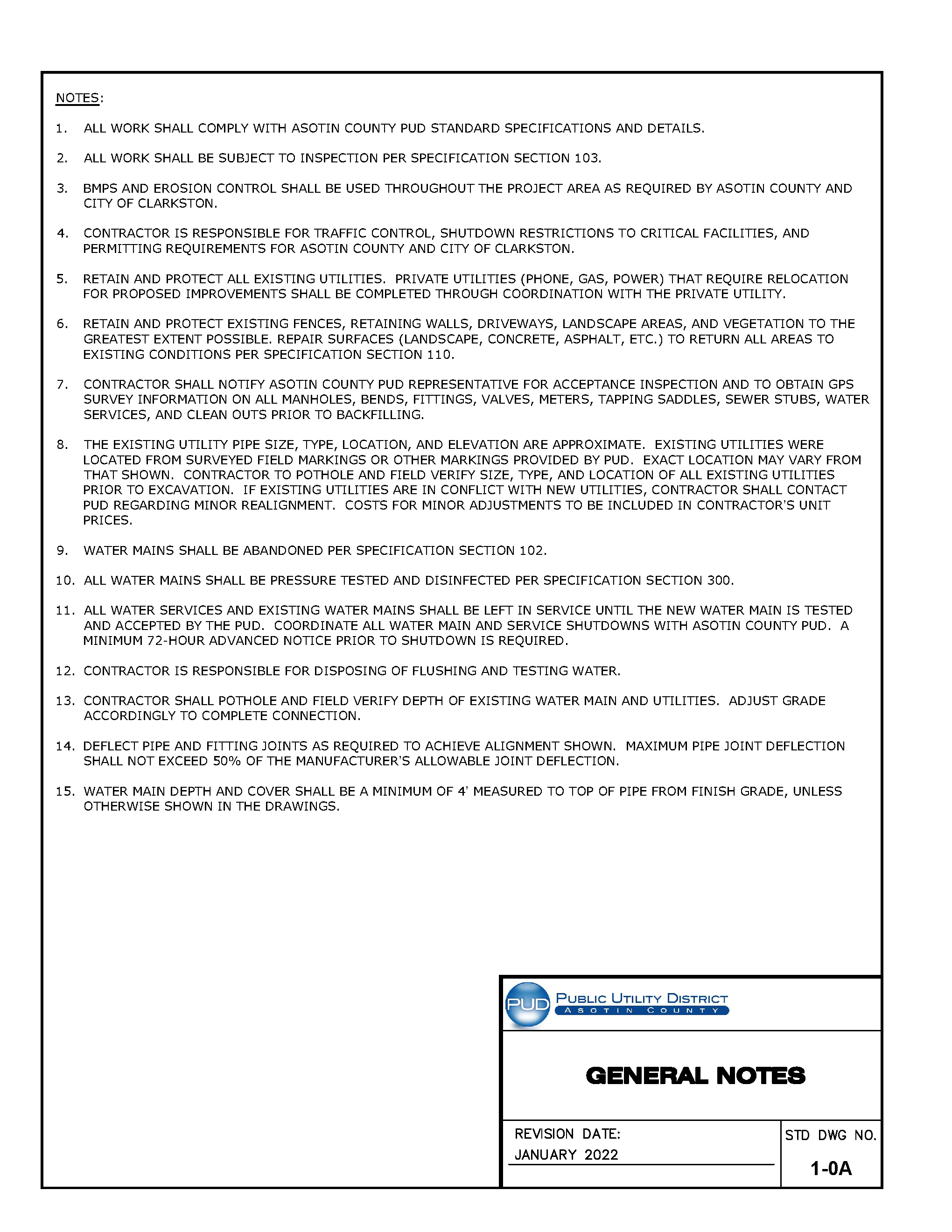
For the original technical drawing, see Construction Standards & Specifications PDF, PDF page 57 of 270.
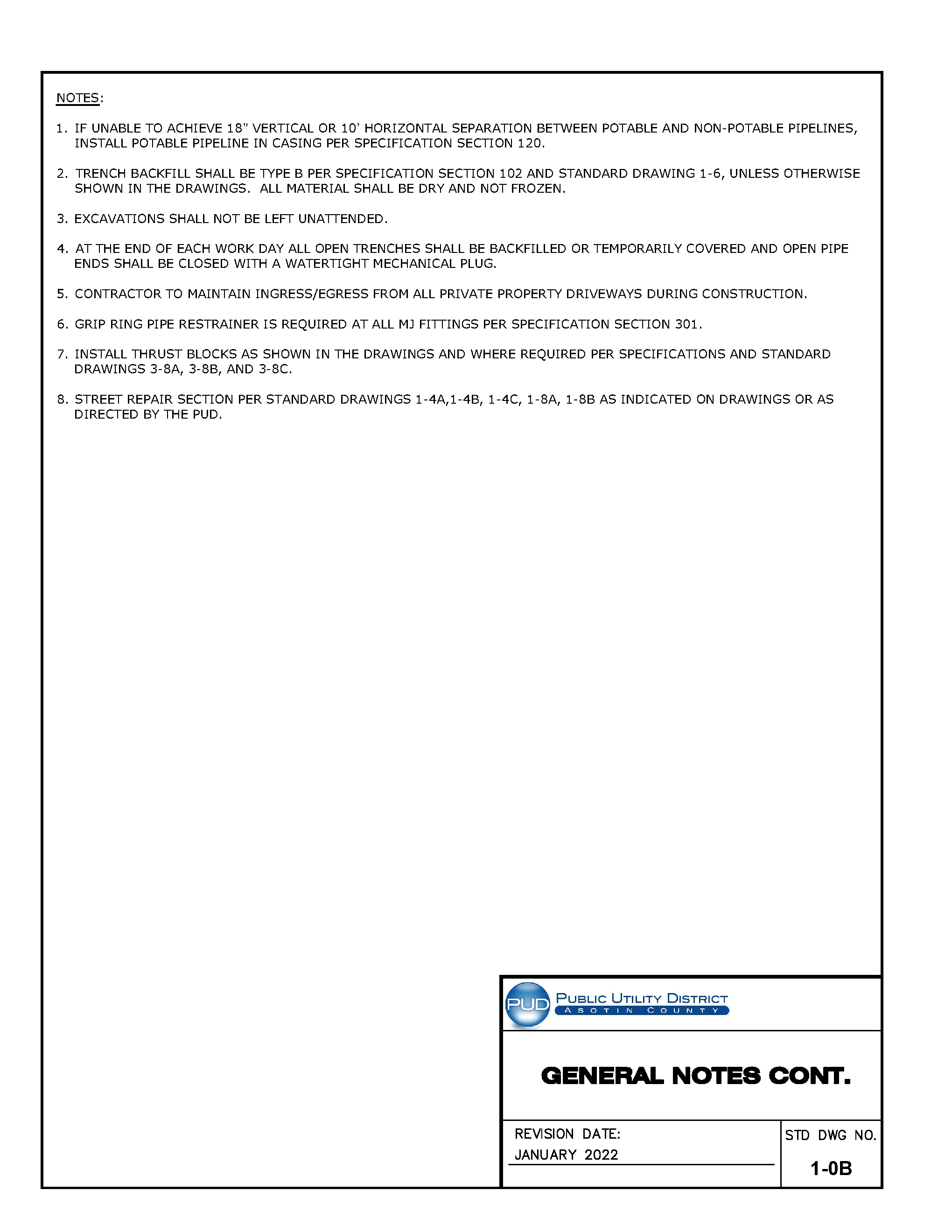
For the original technical drawing, see Construction Standards & Specifications PDF, PDF page 58 of 270.
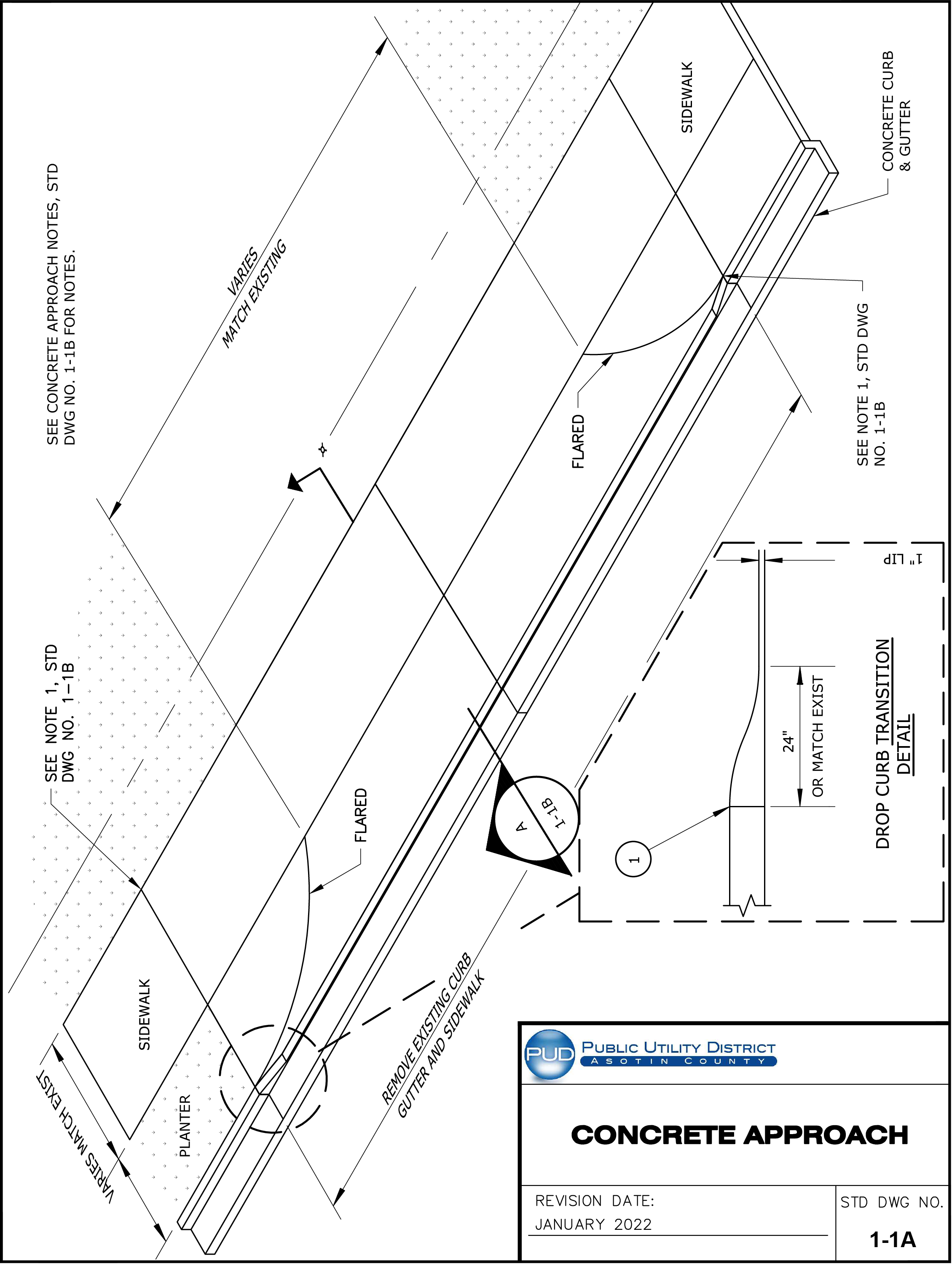
For the original technical drawing, see Construction Standards & Specifications PDF, PDF page 59 of 270.
Accessible drawing description
Drawing labels
- Sidewalk
- Planter
- Concrete curb and gutter
- Flared
- Match existing
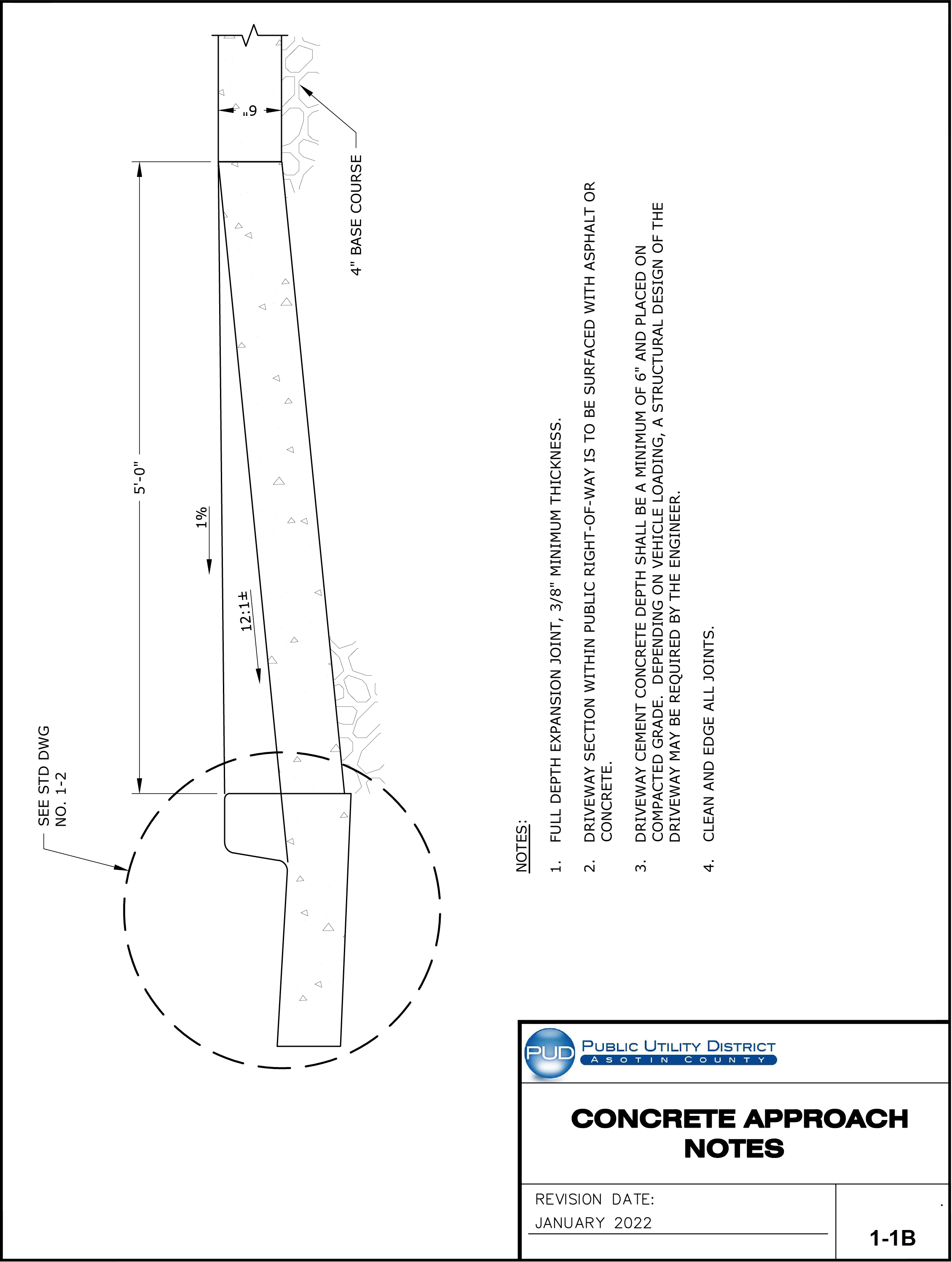
For the original technical drawing, see Construction Standards & Specifications PDF, PDF page 60 of 270.
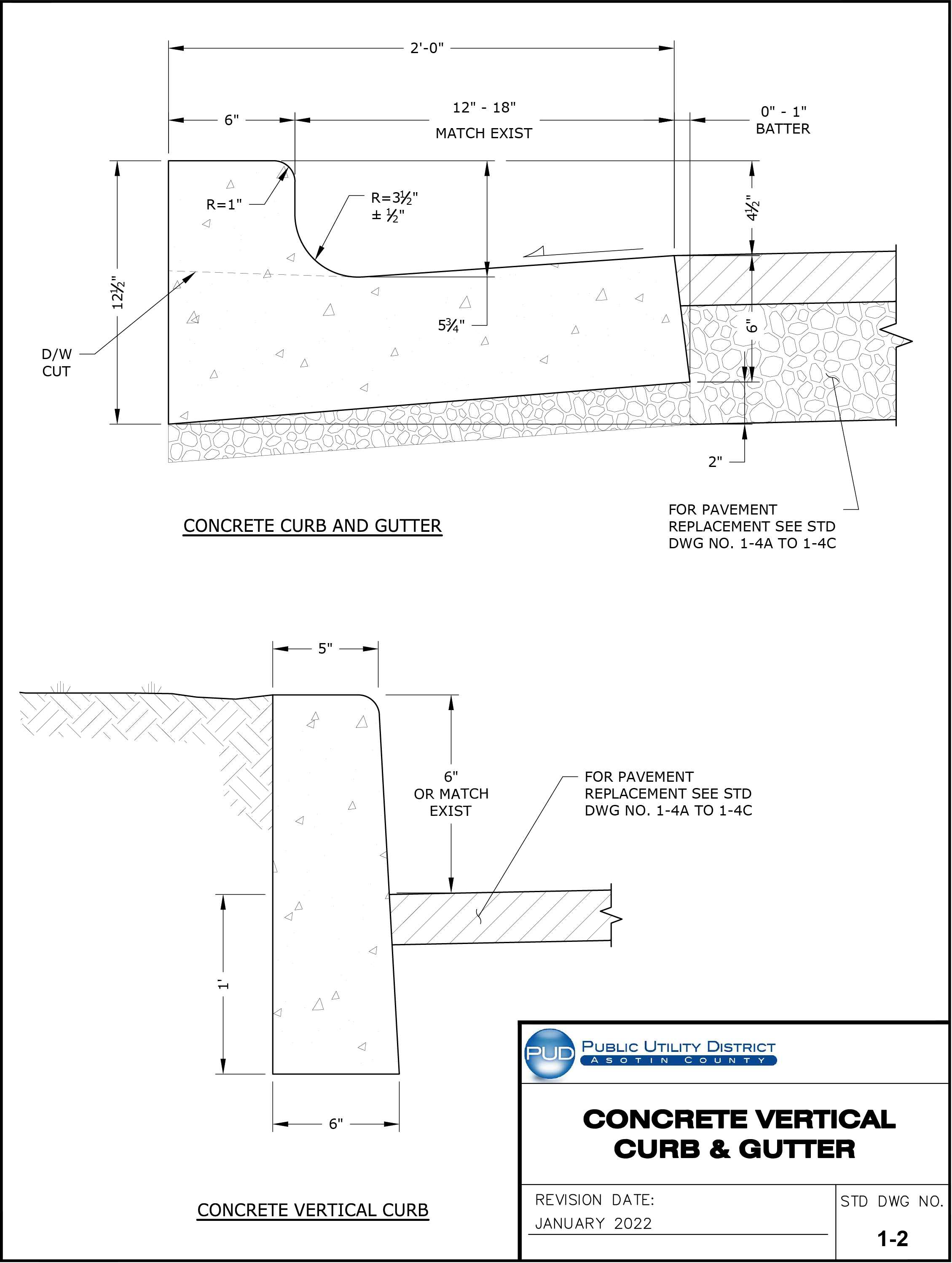
For the original technical drawing, see Construction Standards & Specifications PDF, PDF page 61 of 270.
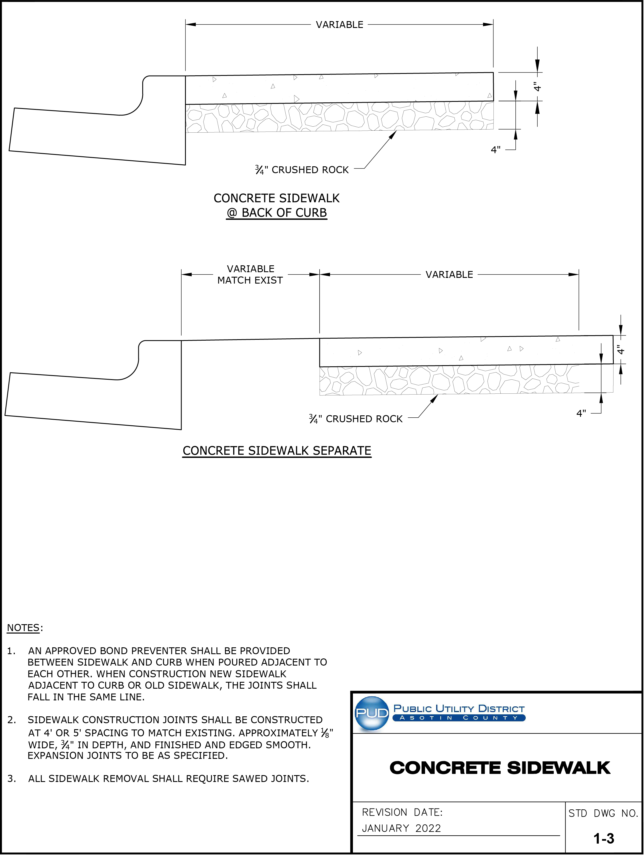
For the original technical drawing, see Construction Standards & Specifications PDF, PDF page 62 of 270.
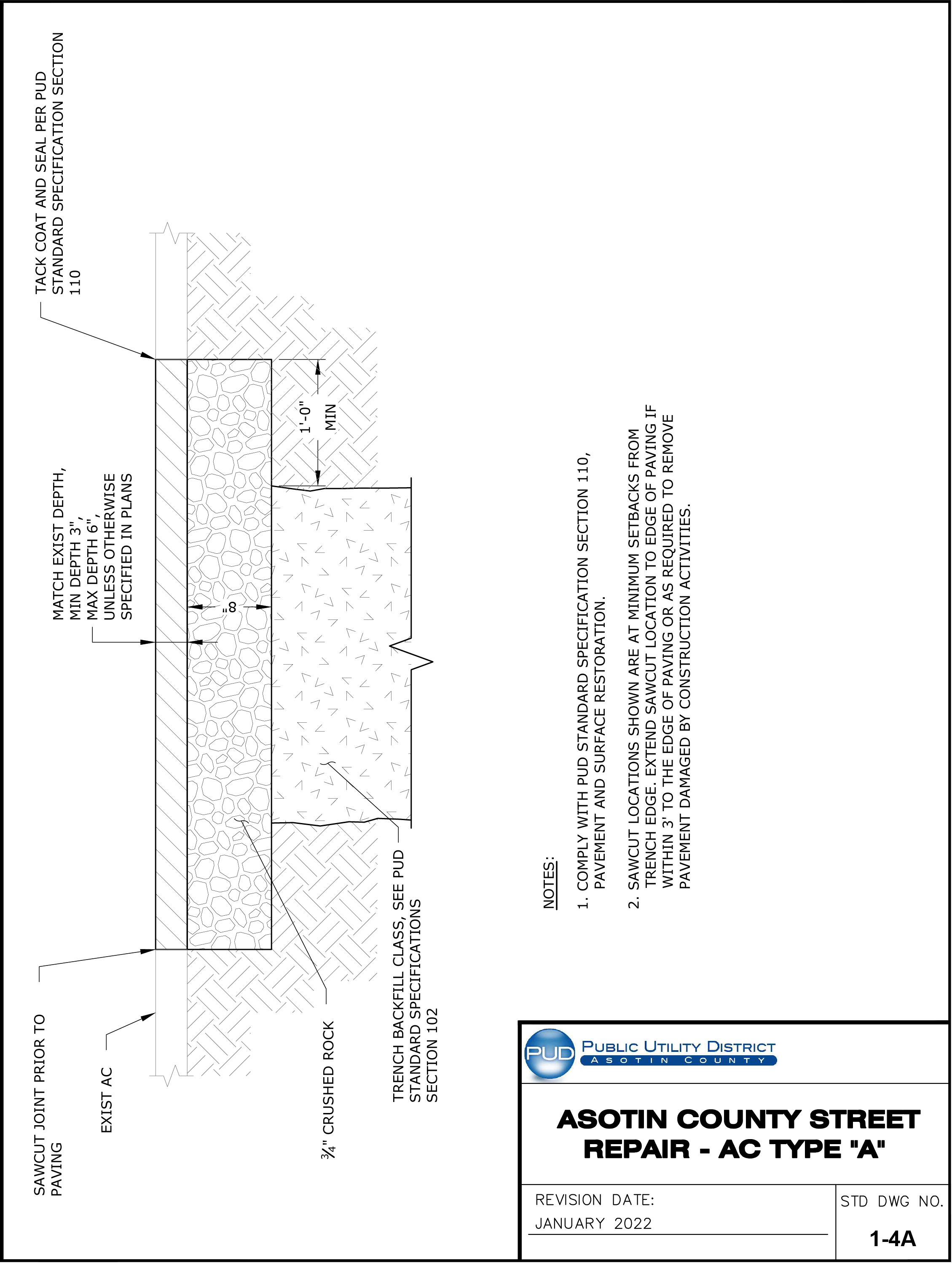
For the original technical drawing, see Construction Standards & Specifications PDF, PDF page 63 of 270.
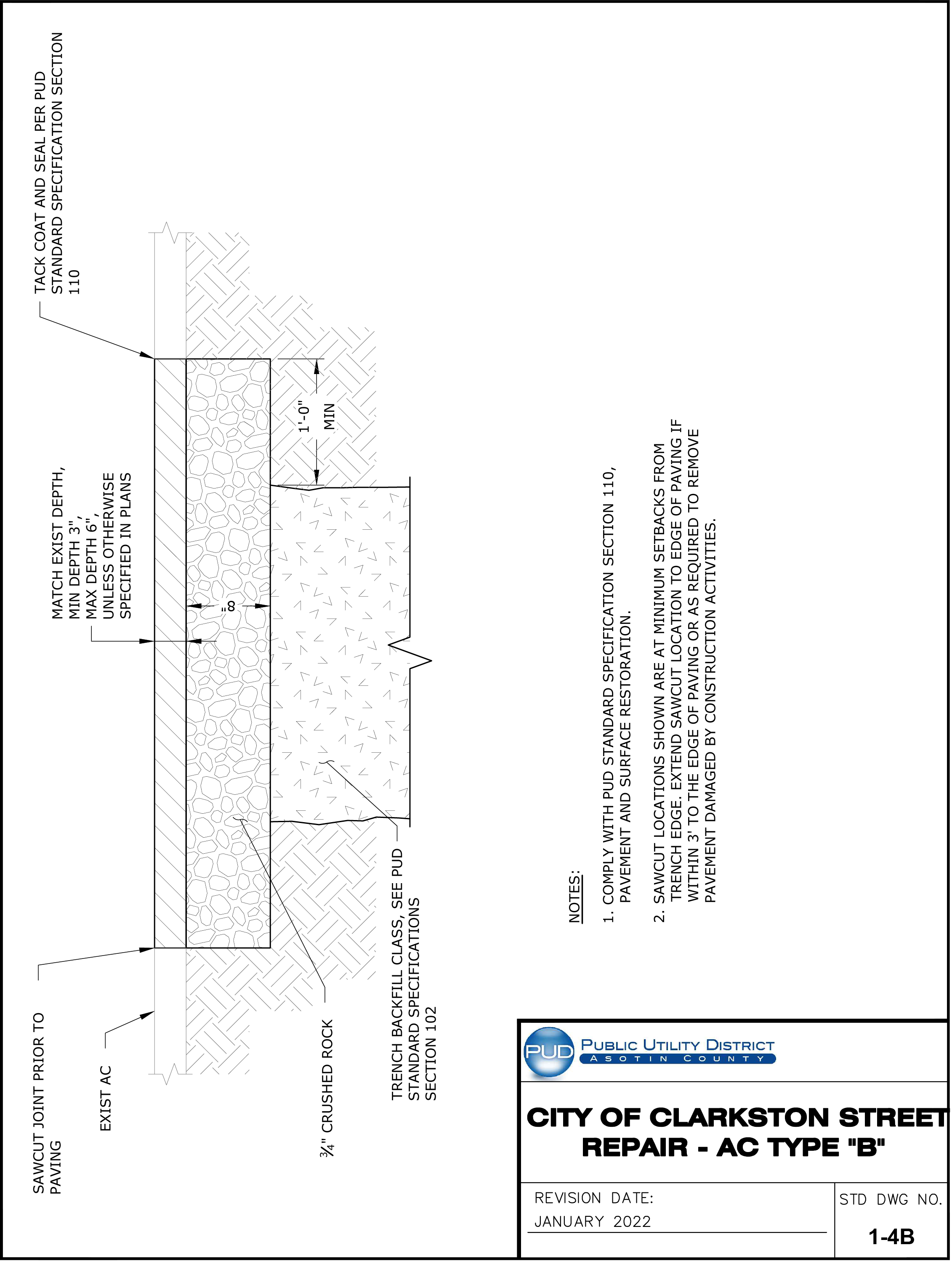
For the original technical drawing, see Construction Standards & Specifications PDF, PDF page 64 of 270.
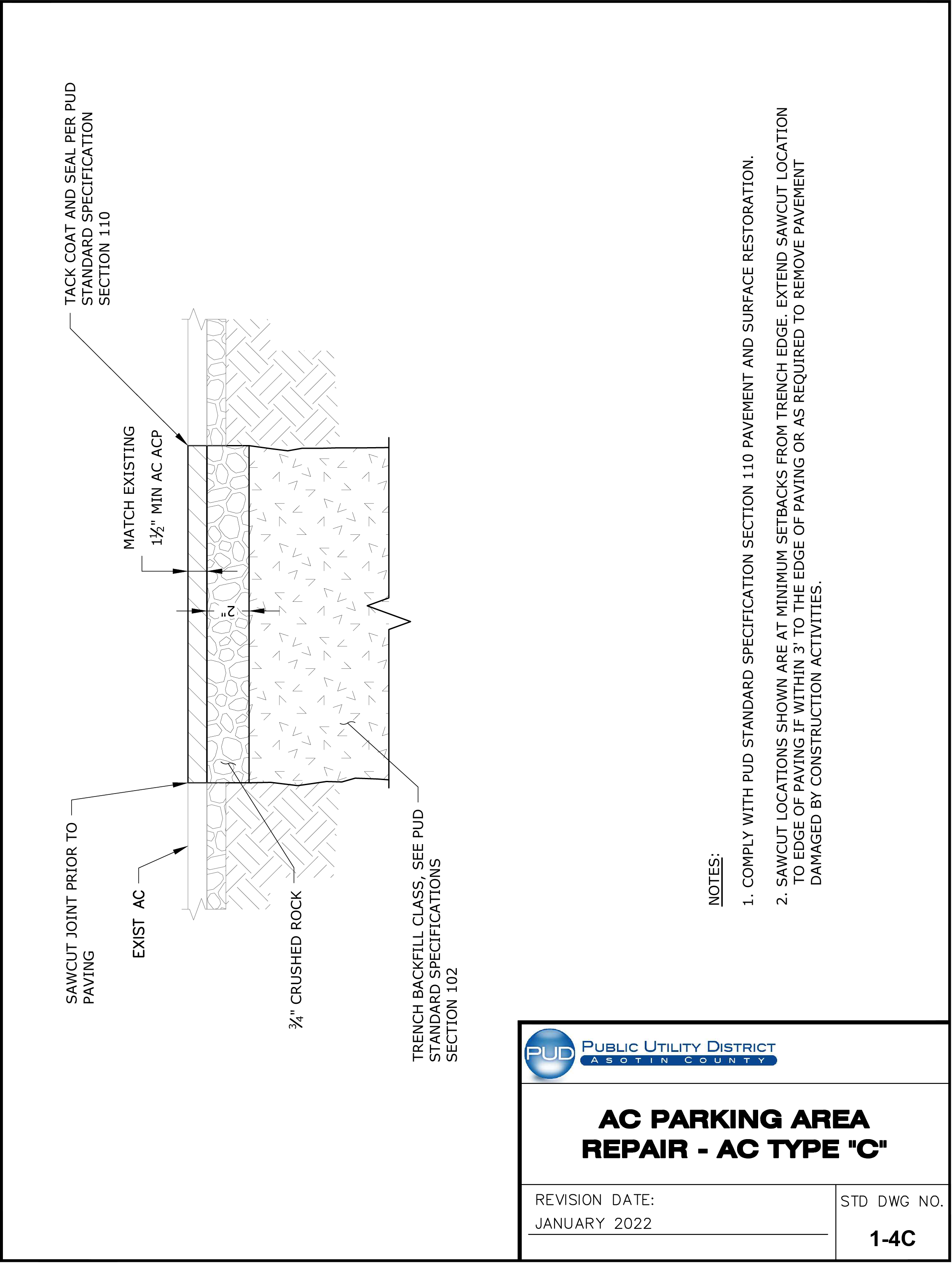
For the original technical drawing, see Construction Standards & Specifications PDF, PDF page 65 of 270.
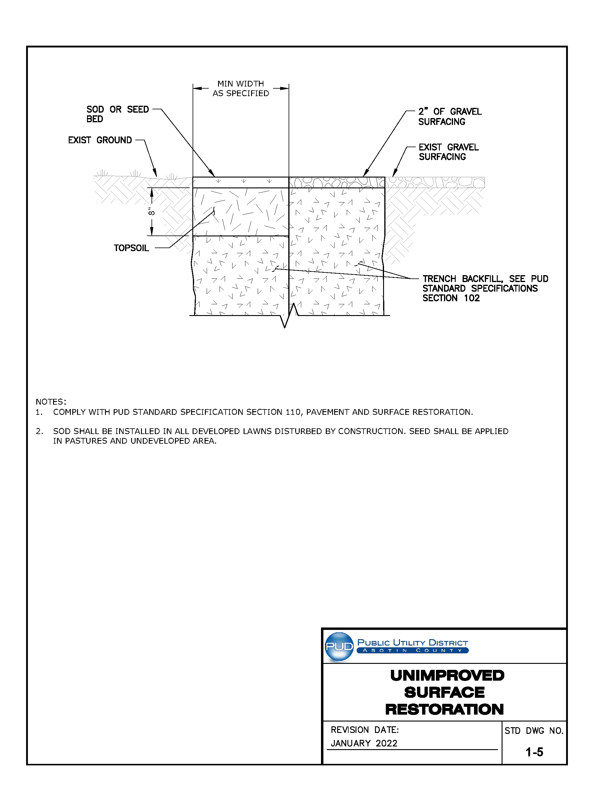
For the original technical drawing, see Construction Standards & Specifications PDF, PDF page 66 of 270.
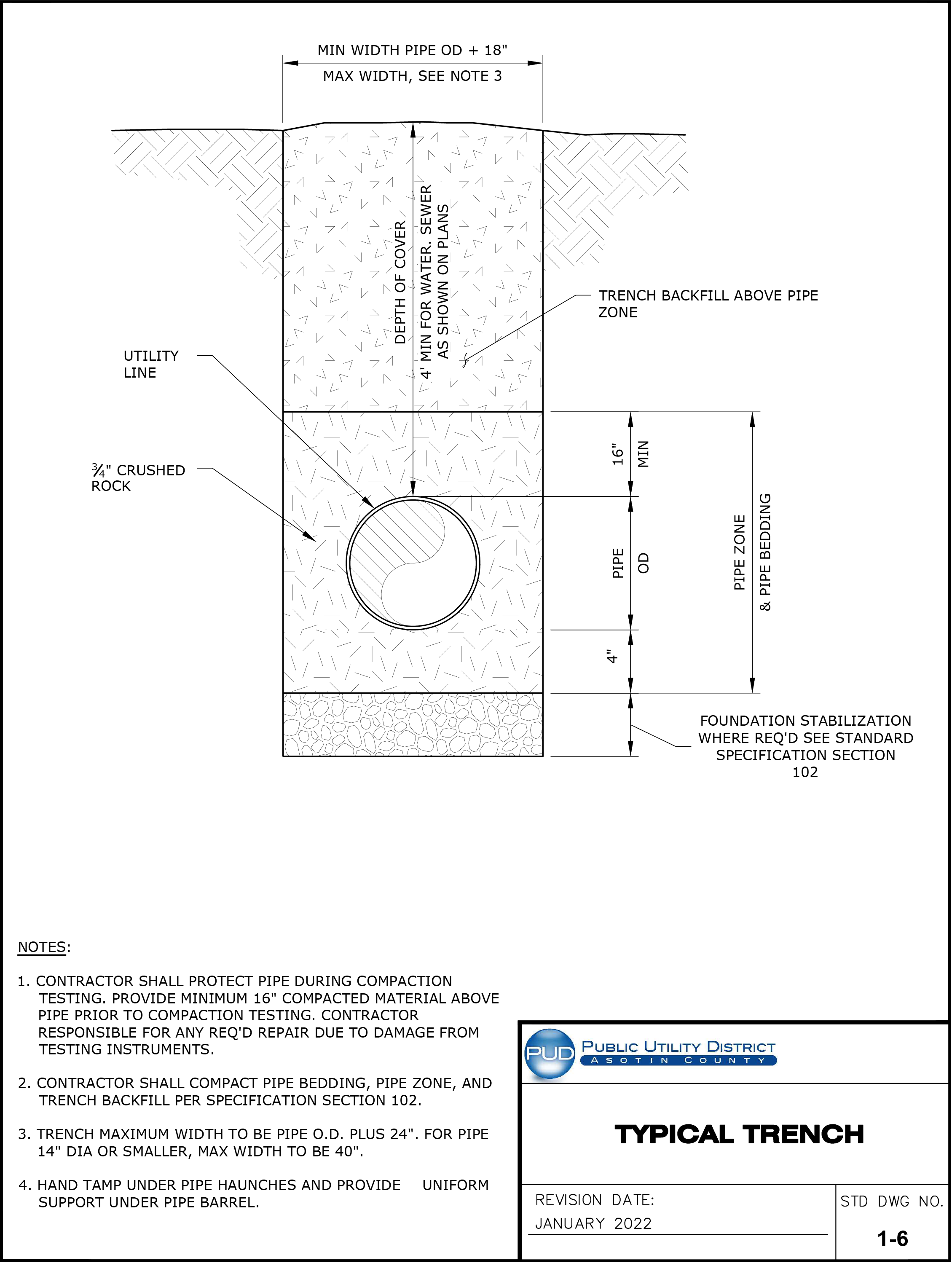
For the original technical drawing, see Construction Standards & Specifications PDF, PDF page 67 of 270.
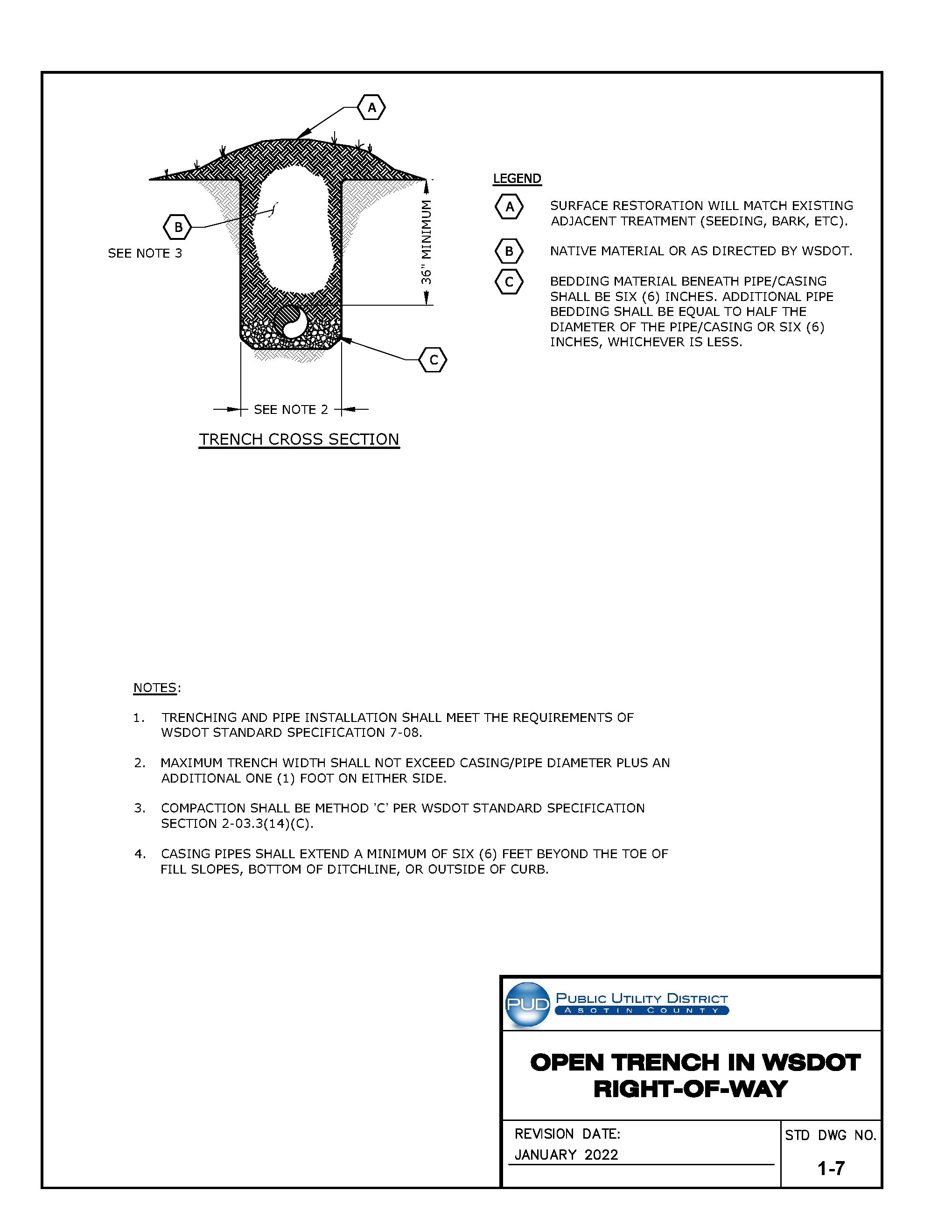
For the original technical drawing, see Construction Standards & Specifications PDF, PDF page 68 of 270.
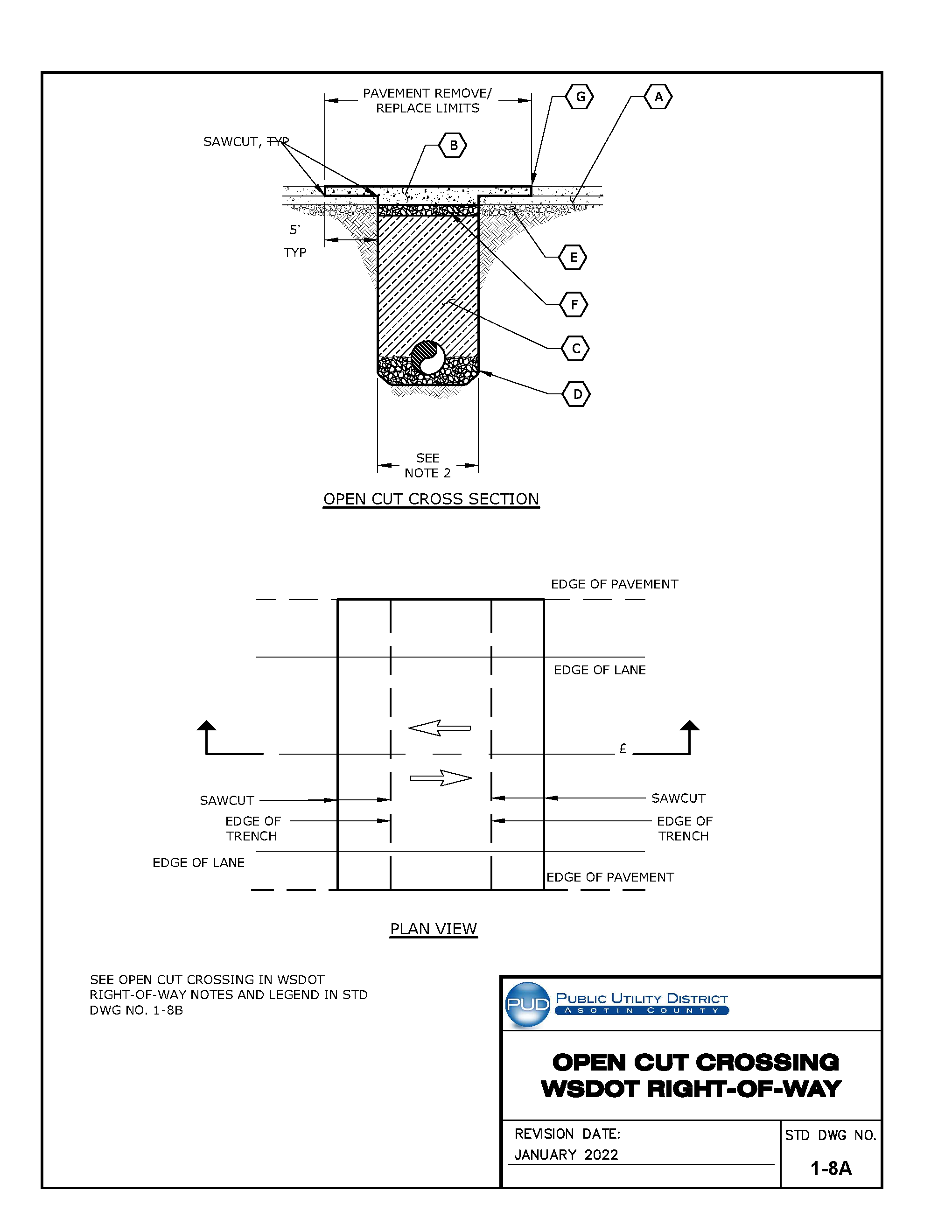
For the original technical drawing, see Construction Standards & Specifications PDF, PDF page 69 of 270.
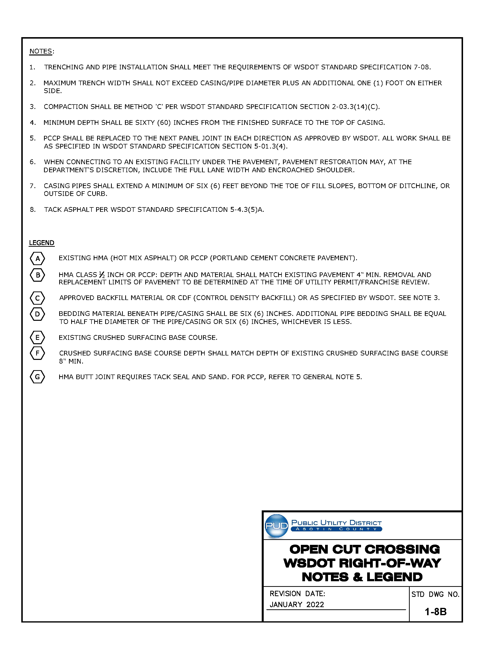
For the original technical drawing, see Construction Standards & Specifications PDF, PDF page 70 of 270.
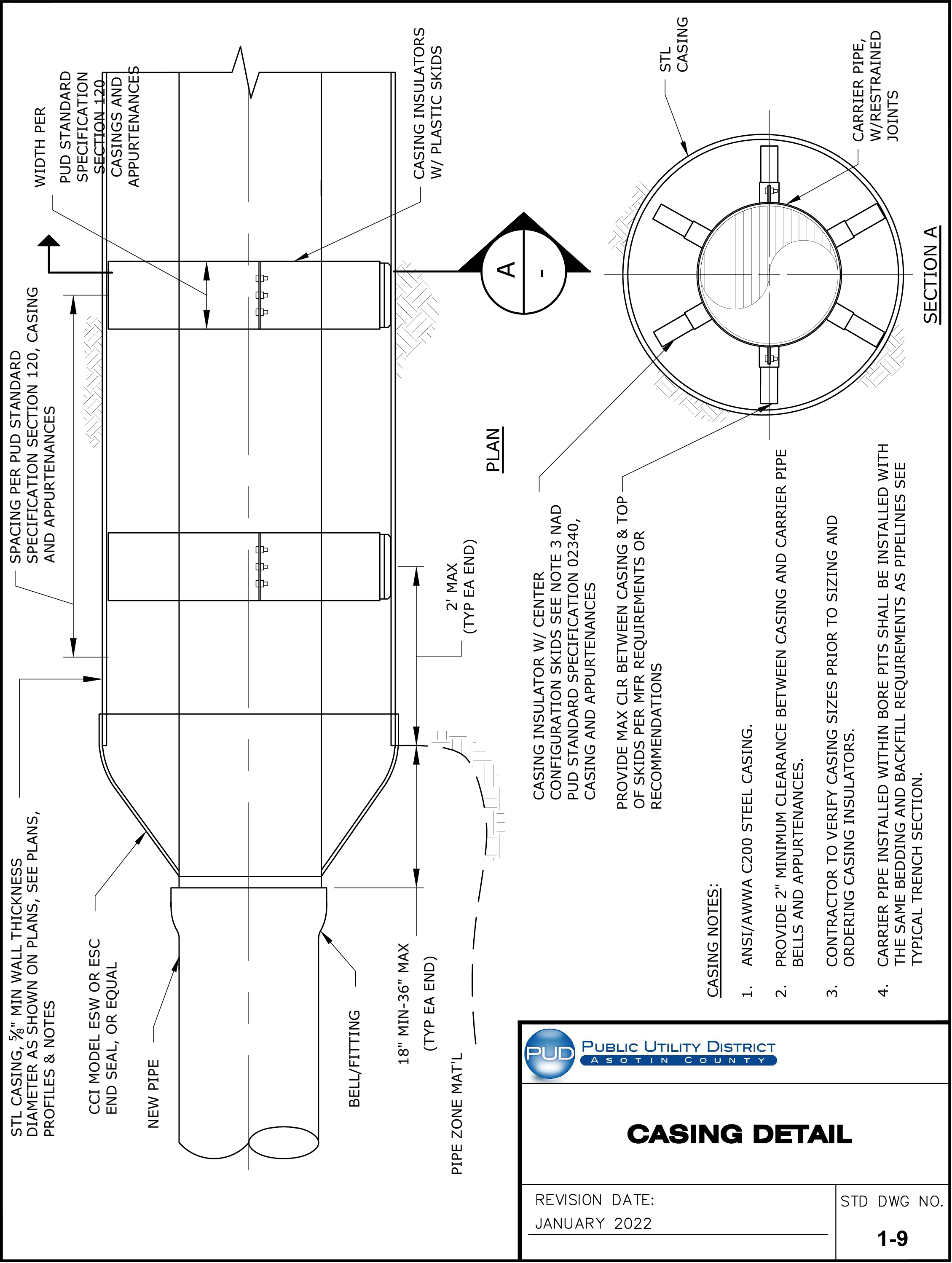
For the original technical drawing, see Construction Standards & Specifications PDF, PDF page 71 of 270.
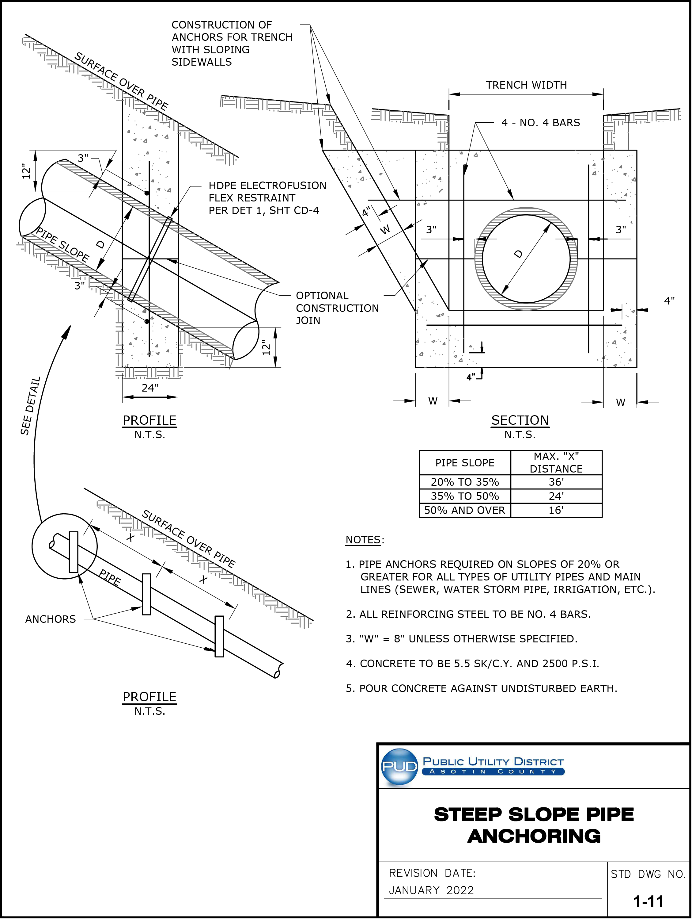
For the original technical drawing, see Construction Standards & Specifications PDF, PDF page 72 of 270.
STANDARD SEWER SPECIFICATIONS AND DRAWINGS
FOR
ASOTIN COUNTY PUD
April 2026
CONSOR 300 E Mallard Drive, Suite 350 Boise, ID 83706 208.639.8185
SECTION 200
PVC PIPE FOR STORM DRAINAGE & SANITARY SEWER
PART 1 GENERAL
1.1 SCOPE
- This section covers polyvinyl chloride (PVC) for gravity storm drainage and sanitary sewer systems. PVC pipe shall be furnished complete with all fittings, joint materials and appurtenances.
Materials to be furnished and installed includes, but is not limited to:
- All pipe, fittings, bends, beveled pipe, adapters, bulkheads, stoppers, plugs, joints restraints, joints and jointing materials and pipe supports.
- Make connections to all existing and/or new facilities and provide temporary services.
- Test and clean pipelines.
1.2 REFERENCES
- ASTM F402: Practice for safe handling of solvent cements and primers used for joining thermoplastic pipe and fittings.
- ASTM D1784: Specification for rigid Poly Vinyl Chloride (PVC) compounds and chlorinated Poly Vinyl Chloride (CPVC) compounds.
- ASTM D2564: Solvent Cements for Poly Vinyl Chloride (PVC) plastic pipe and fittings.
- ASTM D2855: Making Solvent-Cemented joints with Poly Vinyl Chloride (PVC) pipe and fittings.
Reference Standards
- References herein to the “Standard Specifications for Municipal Construction” shall mean the most recent edition of the Washington State Department of Transportation Standard Specifications for Road, Bridge and Municipal Construction.
- References herein to the “Orange Book” shall mean the most recent edition of the most recent edition of the State of Washington Department of Ecology Criteria for Sewage Works Design.
1.3 DELIVERY, STORAGE AND HANDLING
- Comply with requirements of these Specifications.
- Protect the pipe from the sun and provide adequate ventilation.
1.4 SUBMITTALS
- Submit shop Drawings showing: layout plan and dimensions, schedule of pipe fittings and specials, materials and class for each size and type of pipe, joint details, pipe supports and any special provisions required for assembly.
- Product Data: Provide data on pipe, fittings and accessories.
- Provide the pipe manufacturer’s certificate stating that the materials have been sampled and tested in accordance with the provision for and meet the requirements of the designated specification. The certificate shall be signed by an authorized agent of the manufacturer.
- When requested by the Asotin County PUD, certified copies of physical and chemical test results shall be submitted for the materials to be provided.
- Testing results.
PART 2 PRODUCTS
2.1 MATERIALS
Pipe
- In non-pressurized systems, PVC pipe shall be manufactured from rigid polyvinyl chloride compounds conforming to ASTM D-1784, Class 12454-B. PVC pipe and fittings four (4) inches to fifteen (15) inches in diameter shall meet the requirements of ASTM D-3034, SDR 35. PVC pipe eighteen (18) inches and larger in diameter shall conform to ASTM F-679, PS-46. Pipe shall have a minimum stiffness of 46 psi.
- If indicated on the plans (e.g. at potable water crossings), pipe shall be water class pipe and conform to SECTION 102 EXCAVATING, BACKFILLING, AND COMPACTING FOR UTILITIES, UTILITY CROSSINGS.
Side Sewer Pipe (Sewer Laterals):
- Pipe for side sewers may be PVC as specified herein or Schedule 40 DWV pipe, meeting the requirements of ASTM D1785.
Joints
- Non pressurized PVC pipe joints shall be integral bell push-on type meeting the requirements of ASTM D-3212. Gaskets shall be rubber ring type meeting the requirements of ASTM F477. Rubber gaskets shall be factory installed.
- Joints for water class pipe shall conform to SECTION 301 DUCTILE IRON PIPE, FITTINGS AND SPECIAL ITEMS and SECTION 302 PVC PRESSURE PIPE, FITTINGS AND SPECIAL ITEMS.
- Sewer laterals shall be connected by Wye or Romac CB fitting. No tapping of the main line pipe shall be allowed without approval by the owner. Use of Inserta Tee is prohibited unless an exception is obtained by Asotin County PUD.
- Sewer lateral pipe may also be joined by chemical welding or Fernco-style couplings.
PART 3 EXECUTION
3.1 PRODUCT HANDLING
- Care shall be taken in handling and transporting to avoid damaging pipes and their coatings. Loading and unloading shall be accomplished with the pipe under control at all times and under no circumstances shall the pipe be dropped. Pipe shall be securely wedged and restrained during transportation and supported on blocks when stored in the shop or field.
- Storage: Store all pipe on a flat surface so as to support the barrel evenly. It is not recommended that pipe be stacked higher than four (4) feet. Plastic pipe, if stored outside, shall be covered with an opaque material to protect it from the sunlight.
3.2 INSPECTION
- All pipe sections, specials and jointing materials shall be carefully examined for defects and no piece shall be laid that is known to be defective. Any defective piece installed shall be removed and replaced with a new pipe section in a manner satisfactory to the Asotin County PUD at the CONTRACTOR’s expense.
- Defective material shall be marked with black spray paint and removed from the job site before the end of the day.
3.3 SURVEY LINE AND GRADE AND SURVEY MONUMENT REPLACEMENT
- Refer to Section 102 – Excavating, Backfilling, and Compacting for Utilities, Part 3.2.
3.4 PRE-INSTALLATION OPERATIONS
Location of Sewer Laterals
- Existing active sewer laterals shall be marked in the field. The CONTRACTOR shall work with the Asotin County PUD to assist in verifying the status (active or inactive) of any sewer laterals if there is uncertainty as to its status.
- Where indicated on the Drawings, the CONTRACTOR shall provide dye testing to verify active laterals.
Cleaning and CCTV
- Clean the host conduit per Section 220, Sanitary Sewer Main Cleaning and TV Inspection, prior to commencing pipe bursting operations.
- Provide CCTV of the existing line per Section 220, Sanitary Sewer Main Cleaning and TV Inspection, and verify location of services.
3.5 PREPARATION
- Excavate trenches and prepare and maintain subgrade as described in Sections 100, 101, and 102; and as shown on the Plans. Pipe base shall be inspected prior to placement of the pipe. Remove large stones or other hard matter which could damage pipe or impede consistent backfilling or compaction.
- All pipe trenches shall be excavated below the proposed pipe invert as required to accommodate the depths of pipe bedding material as scheduled on the Drawings.
- Remove dirt and foreign material, inside and outside, from pipe and fitting materials before assembly.
- Make straight field cuts without chipping or cracking pipe.
3.6 INSTALLATION
- Install pipe and accessories in accordance with manufacturer’s instructions.
- Lift or roll pipe into position. Do not drop or drag pipe over prepared bedding.
Joints:
All new joints on the main line shall be gasketed. No joints in right-of-way, other than those for sewer laterals, shall be chemically welded or joined with flexible coupling, e.g. Fernco style coupling. Just prior to joining the pipes, the surfaces of the joint rings shall be wiped clean and the joint rings and rubber gaskets shall be liberally lubricated with an approved type of vegetable oil soap. The spigot end, with the gasket placed in the groove, shall be entered into the bell of the pipe already laid, making sure that both pipes are properly aligned.
Before the joint is fully “home,” the position of the gasket in the joint shall be determined by means of a suitable feeler gauge supplied by the pipe manufacturer. If the gasket is found not to be in proper position, the pipes shall be separated and the damaged gasket replaced. The pipe is then forced “home” firmly and fully. In its final position, the joint between the pipes shall not be deflected more than 1/2-inch at any point.
Install pipe and fittings to the line and grade specified on the Drawings with bell end upstream, joints centered, spigots home, pipe properly supported and restrained against movement and all valve stems plumb.
- Where longitudinal slopes are 20% or greater, all pipe joints shall be restrained. Anchor blocks shall be used in conjunction with pipe joint restraint. Anchor blocks shall be 12 inches long and shall encase the pipe 12 inches thick at a minimum. Anchor blocks shall be placed 20 feet on center.
- On unpaved slopes 20% or greater, timber baffles/hill holders shall be required at a maximum spacing of 18 feet on center, and a minimum of one (1) timber baffle/hill holder per each pipe length.
- Lay pipe from the low end toward the high point. Provide a continuous, smooth invert. Bell holes shall be dug where necessary to ensure pipe lays flat and the pipe shall be placed and supported on bedding material the full length of the barrel.
- All loose dirt shall be removed from the bottom and the trench backfilled with specified bedding material to pipe laying grade.
- Variance from the established line and grade shall not be greater than 1/32-inch per inch of pipe diameter and shall not exceed 1/2-inch for line and 1/4-inch for grade, providing that such variation does not result in a level or reverse-sloping invert. Variation in the invert elevation between adjoining ends of pipe, including fittings, shall not exceed 1/64-inch per inch of pipe diameter, or 1/2-inch maximum.
- The open ends of all pipes and special castings shall be plugged or otherwise closed with a watertight plug before leaving the work for the night, and at other times of interruption of the work. All pipe ends which are to be permanently closed shall be plugged or capped and restrained against internal pressure.
- Side sewers shall be constructed with a maximum joint deflection not to exceed the manufacturer’s printed recommendations and in no case shall exceed two (2) inches per foot in any joint. Larger changes in direction shall be made by use of standard ⅛ bends.
- Side sewers shall be connected to the wye provided in the public sewer, where such is available, utilizing approved fittings or adapters. Where no wye or riser is provided or available, connection shall be made by machine made tap and Romac CB or other approved saddle with owner approval.
- Side sewers shall not be constructed on private property prior to completion and acceptance of the main line and side sewer on public Right of Way or easement unless approved in writing by the Asotin County PUD.
- The location of side sewers at the property line shall be marked by the CONTRACTOR with a metal post four (4) feet long buried in the ground to the depth of the sewer lateral or three (3) feet, whichever is greater. The metal post shall be installed at the end of the sewer cap and extend above grade a minimum of one (1) foot regardless of lateral depth. The bottom end shall have a wood 2 by 4 inch post nailed to it to prevent withdrawal of the post. The exposed end shall be painted traffic white and the depth to the side sewer or tee shall be indicated in black paint on the metal post. In addition, a length of 12-gauge tracer wire shall be provided to extend from the sewer main end of the side sewer and shall emerge at the 4-foot metal post, but shall not be fastened to it. Provide a safety cap for the metal post.
- Side sewer cleanouts shall be provided at the property line and for each total change of 90 degrees of grade or alignment and in no case shall the spacing of cleanouts exceed 100 feet. No cleanout will be required at the connection of the side sewer to a riser on the public sewer. Cleanouts shall consist of a wye branch in the side sewer.
- All cleanouts located in public rights of way shall be extended to grade. The extension of cleanouts to grade on private property will be optional with the property owner. When extended to grade, cleanouts shall be full side sewer diameter and shall be extended per Standard Drawing 2-8. A 1/8 bend shall be used to deflect the side sewer upward at a cleanout where the terminal end of the side sewer lies upstream from the last point of connection.
3.7 PIPELINE INSPECTION
- General: All sanitary sewer lines shall be inspected by the use of a television camera before final acceptance. The sewer line shall be hydro flushed immediately prior to television camera inspection. Remove debris at the nearest downstream manhole rather than washing them downstream. The costs incurred in making the initial inspection shall be borne by the owner of the sanitary sewer.
- The CONTRACTOR shall bear all costs incurred in correcting any deficiencies found during television inspection, including the cost of any additional television inspection that may be required by the Asotin County PUD to verify the correction of said deficiency. The CONTRACTOR shall be responsible for all costs incurred in any television inspection performed solely for the benefit of the CONTRACTOR.
Acceptance Criteria:
If standing water in pipeline is observed due to grade defects, use the following table to determine allowable depth of standing water in relationship to the design slope of pipe.
Pipeline Slope (ft/ft) Allowable standing Water Depth (inch) Slope < 0.001 ≤5/8” 0.001 < Slope ≤ 0.002 ≤1/2” 0.002 < Slope ≤ 0.004 ≤3/8” 0.004 < Slope ≤ 0.006 ≤1/4” 0.006 < Slope ≤ 0.008 No Standing Water
3.8 PIPELINE TESTING
General:
- All pipelines shall be subject to acceptance tests. The CONTRACTOR shall provide necessary utilities, labor and facilities for testing and shall dispose of waste, including water.
- Sewers and appurtenances shall be cleaned and tested after backfilling by either the exfiltration or low pressure air method at the option of the CONTRACTOR, except where the ground water table is such that the Asotin County PUD may require the infiltration test. For either the infiltration or exfiltration test, all lateral or side sewer branches included in the test section shall be taken into account in computing allowable leakage. An allowance of 0.2 gallons per hour per foot of head above invert shall be made for each manhole included in a test section. Upon final acceptance of the work all sewers, side sewers and fittings shall be open, clean and free draining.
- All work involved in cleaning and testing sewer lines between manholes or rodding inlets shall be completed within fifteen (15) working days after backfilling of sewer lines and structures. Any further delay will require the written consent of the Asotin County PUD. The CONTRACTOR shall furnish all labor, materials, tools and equipment necessary to make the test, clean the lines and perform all incidental work. The CONTRACTOR shall perform the tests under the direction and in the presence of the Asotin County PUD. Precautions shall be taken to prevent joints from drawing during tests, and any damage resulting from these tests shall be repaired by the CONTRACTOR at no expense to the Asotin County PUD. The manner and time of testing shall be subject to approval by the Asotin County PUD.
- All wyes, tees and stubs shall be plugged with flexible jointed caps, or acceptable alternate, securely fastened to withstand the internal test pressure. Such plugs or caps shall be readily removable, and their removal shall provide a socket suitable for making a flexible jointed lateral connection or extension.
If any sewer installation fails to meet the requirements of the test method used, the CONTRACTOR shall determine, at no expense to the Asotin County PUD, the source or sources of leakage and shall repair or replace all defective materials or workmanship at no expense to the Asotin County PUD. The complete pipe installation shall meet the requirements of the test method used before being considered acceptable.
Side Sewers:
- Shall be tested after backfilling and if constructed in conjunction with the main sewer shall, for purposes of testing, have a 6-inch tee fitting pipe placed at the point where the side sewer crosses the street or other public Right of Way margin. The tee opening shall be positioned perpendicular to the side sewer slope, unless otherwise directed by the Asotin County PUD.
- When side sewers are not tested simultaneously with the testing of the main sewer, the CONTRACTOR, at no expense to the Asotin County PUD, shall furnish and place an additional tee in the first pipe out of the main sewer tee or wye branch, so that an inflatable rubber ball can be inserted for sealing off the side sewer and thus permit separate tests.
- Testing side sanitary sewers shall be, for their entire length, from the public sewer in the street to the connection with the building’s plumbing. Their testing shall be as required by the local sanitary agency but in no case shall it be less thorough than that of filling the pipe with water before backfilling and visually inspecting the exterior for leakage. The decision of the Asotin County PUD as to acceptance of the side sanitary sewer shall be final.
Testing
Exfiltration Test
- Prior to making exfiltration leakage tests, the CONTRACTOR may fill the pipe with clear water to permit normal absorption into the pipe walls provided, however, that after so filling the pipe, the CONTRACTOR shall complete the leakage test within 24 hours after filling. When under test, the allowable leakage shall be limited according to the provisions that follow. Specified allowances assume pre-wetted pipe.
- Leakage shall be no more than 0.28 gph per inch diameter per 100 feet of sewer, with a hydrostatic head of six (6) feet above the crown at the upper end of the test section, or above the natural ground water table at the time of test, whichever is higher. The length of pipe tested shall be limited so that the pressure at the lower end of the section tested does not exceed 16 feet of head above the invert, and in no case shall be greater than 700 feet or the distance between manholes when greater than 700 feet.
Where the test head is other than six (6) feet, the maximum leakage shall not exceed the amount determined from the following equation:

For the original equation in context, see Construction Standards & Specifications PDF, PDF page 82 of 270.
Where:
D= diameter (in.)L= length of pipe (ft.)H= test head (ft.)- When the test is to be made one joint at a time, the leakage per joint shall not exceed the computed allowable leakage per length of pipe.
Infiltration Test
- Where the natural ground water head over the pipe is two (2) feet or less above the crown of pipe at the upper end of the test section, the infiltration test leakage shall not exceed 0.16 gallons per hour per inch of diameter per 100 feet of pipe length. The length of pipe tested shall not exceed 700 feet or the distance between manholes when greater than 700 feet.
Where the natural ground water head is greater than two (2) feet, the maximum leakage shall not exceed the amount determined from the following equation:

For the original equation in context, see Construction Standards & Specifications PDF, PDF page 83 of 270.
Where:
D= diameter (in.)L= length of pipe (ft.)H= test head (ft.)
- When a suitable head of ground water exists above the crown of the pipe and when the pipe is large enough to work inside, acceptance may be based on the repair of visible leakage by means satisfactory to the Asotin County PUD.
Low Pressure Air Test for Sanitary Sewers Constructed of Air Permeable Materials
- Low pressure air testing may be used on pipes 30 inches in diameter and smaller. The test equipment to be used shall be furnished by the CONTRACTOR and shall be inspected and approved by the Asotin County PUD prior to use. The Asotin County PUD may at any time require a calibration test of gauges or other instrumentation that is incorporated into the test equipment. Calibration tests shall be certified by an independent testing laboratory.
Plugs used to close the pipe for the air test must be securely braced to prevent the unintentional release of a plug, which can become a high velocity projectile. Gauges, air piping manifold and valves shall be located at the top of the ground. No one shall be permitted to enter a manhole or catch basin where a plugged pipe is under pressure. Air testing apparatus shall be equipped with a pressure release device, such as a rupture disk or a pressure relief valve, designed to activate when the pressure in the pipe exceeds two (2) psig above the required test pressure.
- If the pipe to be tested is submerged by groundwater, the backpressure on the pipe created by the groundwater submergence must be determined. All gauge pressures described in the test shall be increased by that amount.
- The first section of pipe installed by each crew shall be tested in order to qualify the crew and material. A successful test for the section shall be a prerequisite to further installation by that crew. Following the initial test, pipes shall be tested from manhole to manhole, catch basin to catch basin or such shorter lengths as determined by the CONTRACTOR.
- Air shall be slowly supplied to the plugged pipe section until the internal air pressure reaches four (4) psig. At no point should the air pressure be allowed to exceed nine (9) psig. Wait at least two (2) minutes to allow for pressure and temperature stabilization to occur within the pipe.
- When the pressure decreases to 3.5 psig, the air pressure test shall begin. The test shall consist of measuring the time in seconds for the pressure in the pipe to drop from 3.5 psig to 2.5 psig. Acceptance for pipe constructed of air permeable materials, shall be if the time in seconds for the pressure drop is equal to or greater than the required time as calculated below.

For the original equation in context, see Construction Standards & Specifications PDF, PDF page 84 of 270.

For the original equation in context, see Construction Standards & Specifications PDF, PDF page 84 of 270.
If CT < 1, then time = KT

For the original equation in context, see Construction Standards & Specifications PDF, PDF page 84 of 270.
Where:
d = Pipe diameter (inches) L = Pipe length (feet) K = value for each length of pipe of a specific diameter C = value for each length of pipe of a specific diameter KT = K1 + K2 +… = sum of all K values CT = C1 + C2 +… = sum of all C values
Table: Low Pressure Air Test for Air Permeable Materials Minimum Test Times in Seconds for Pressure Drop From 3.5 to 2.5 psig (1 psig)
| Distance Between Manholes (feet | Nominal Pipe Diameter (inch) | |||||||||
|---|---|---|---|---|---|---|---|---|---|---|
| 6 | 8 | 10 | 12 | 15 | 18 | 21 | 24 | 27 | 30 | |
| 100 | 40 | 71 | 111 | 160 | 250 | 360 | 490 | 639 | 765 | 850 |
| 150 | 60 | 107 | 167 | 240 | 375 | 510 | 595 | 680 | 765 | 856 |
| 200 | 80 | 142 | 222 | 320 | 425 | 510 | 595 | 731 | 925 | 1142 |
| 250 | 100 | 178 | 278 | 340 | 425 | 514 | 699 | 913 | 1156 | 1427 |
| 300 | 120 | 213 | 283 | 340 | 428 | 617 | 839 | 1096 | 1387 | 1713 |
| 350 | 140 | 227 | 283 | 340 | 500 | 719 | 979 | 1279 | 1618 | 1998 |
| 400 | 160 | 227 | 283 | 365 | 571 | 822 | 1119 | 1461 | 1850 | 2283 |
| 450 | 170 | 227 | 285 | 411 | 642 | 925 | 1259 | 1644 | 2081 | 2569 |
| 500 | 170 | 227 | 317 | 457 | 714 | 1028 | 1399 | 1827 | 2312 | 2854 |
| 550 | 170 | 227 | 349 | 502 | 785 | 1130 | 1538 | 2009 | 2543 | 3140 |
| 600 | 170 | 244 | 381 | 548 | 856 | 1233 | 1678 | 2192 | 2774 | 3425 |
- This method was developed based on an allowable air loss rate of 0.003 cubic feet per minute (cfm) per square foot of internal pipe surface, with the total air loss rate not less than 2 cfm nor greater than 3.5 cfm. At the CONTRACTOR’s option, the pipe may be tested without pre‑wetting; however, the allowable air loss rate assumes pre-wetted pipe.
- Pipe over 30 inches in diameter shall be tested one joint at a time in accordance with ASTM C1103
Low Pressure Air Test for Sanitary Sewers Constructed of Non Air Permeable Materials
- Non air permeable materials include ductile iron, ABS composite, polyvinyl chloride (PVC), and polyethylene (PE). When non air permeable pipe is subjected to a low-pressure air test, all of the provisions of Section 200, Part 3.8 C.3. shall apply, except that the time in seconds for the pressure drop shall be equal to or greater than four times the required time calculated in Section 200, Part 3.8 C.3.
- Pipe over 30 inches in diameter shall be tested one joint at a time in accordance with ASTM C1103.
- Reaches of thermoplastic pipe containing no joints shall be exempt from testing requirements.
Table: Low Pressure Air Test for Non Air Permeable Materials Minimum Test Times in Seconds for Pressure Drop From 3.5 to 2.5 psig (1 psig)
| Distance Between Manholes (feet | Nominal Pipe Diameter (inch) | |||||||||
|---|---|---|---|---|---|---|---|---|---|---|
| 6 | 8 | 10 | 12 | 15 | 18 | 21 | 24 | 27 | 30 | |
| 100 | 160 | 284 | 444 | 639 | 999 | 1439 | 1958 | 2557 | 3060 | 3400 |
| 150 | 240 | 426 | 666 | 959 | 1499 | 2040 | 2380 | 2720 | 3060 | 3425 |
| 200 | 320 | 568 | 888 | 1279 | 1700 | 2040 | 2380 | 2923 | 3699 | 4567 |
| 250 | 400 | 710 | 1110 | 1360 | 1700 | 2055 | 2797 | 3653 | 4624 | 5709 |
| 300 | 480 | 852 | 1133 | 1360 | 1713 | 2466 | 3357 | 4384 | 5549 | 6850 |
| 350 | 559 | 907 | 1133 | 1360 | 1998 | 2877 | 3916 | 5115 | 6474 | 7992 |
| 400 | 639 | 907 | 1133 | 1461 | 2283 | 3288 | 4476 | 5846 | 7398 | 9134 |
| 450 | 680 | 907 | 1142 | 1644 | 2569 | 3699 | 5035 | 6576 | 8323 | 10275 |
| 500 | 680 | 907 | 1269 | 1827 | 2854 | 4110 | 5594 | 7307 | 9248 | 11417 |
| 550 | 680 | 907 | 1395 | 2009 | 3140 | 4521 | 6154 | 8038 | 10173 | 12559 |
| 600 | 680 | 974 | 1522 | 2192 | 3425 | 4932 | 6713 | 8768 | 11097 | 13701 |
Deflection Testing for Flexible Pipe (Mandrel Test)
- If required by the Contract Documents, deflection test all flexible pipelines no sooner than 30 days after trench backfill and compaction is completed. Unless otherwise provided in the contract, the Contractor shall bear costs associated with completing surface repair or wither work prior to all required testing. The maximum allowable deflection is to be 5.0% of the nominal pipe diameter.
- Provide test mandrels with a diameter at least 95% of the actual inside diameter (ID) of the pipe. For pipes with controlled outside diameter, calculate the actual ID of the pipe by taking the average outside diameter (OD) as set by the ASTM standard and subtracting 2 times the minimum wall thickness as set by the ASTM standard. For pipes with control inside diameter, use the ID set by the ASTM Standard.
Pull the appropriate mandrel through the pipe using one of the following methods:
- Pull the mandrel through the pipe by hand. If the pipe will not allow the mandrel to pass, repeat the test from the opposite direction to determine the limits of failure.
As a part of the CCTV inspection, pull the mandrel through the pipe by connecting it in front of the CCTV camera lens at a distance equal to the camera’s focal length. Notify Engineer of time and date of test at least 1 day (24 hours) prior to testing to allow for Engineer, at Engineer’s discretion, to witness test. Provide tag line to reverse mandrel and camera should mandrel fail to pass through line. Perform test as a separate step from the CCTV inspection thus a separate DVD record must be made of the mandrel test. Clearly mark DVD identifying project name, mandrel test. If the pipe will not allow the mandrel to pass, repeat the test from the opposite direction to determine the limits of failure.
- Uncover and, if required by the Engineer, remove and reinstall new pipe section for reaches with excessive deflection or recompact bedding if, in the opinion of the Engineer, existing pipe is not damaged. Retest pipe after any repair work is completed. Do not reinstall damaged pipe.
- Use a “Go-Nogo” pin gauge instead of a mandrel if “Insta-Tap” tee fittings are used for service connections. Use test diameter per 4.b above.
- The Asotin County PUD may conduct additional deflection testing prior to expiration of the warranty period. Uncover and reinstall sections of the pipe found to have excessive deflection. Do not reinstall damaged pipe.
Test Results
- The CONTRACTOR shall notify the Asotin County PUD three (3) days prior to testing and submit testing data to the Asotin County PUD.
3.9 PIPE ABANDONMENT AND REMOVAL
- Pipe to be removed shall be cut off at the berm intersection or where indicated on plans. Remaining cut end and abandoned pipe shall be properly plugged watertight with fittings or masonry plug.
3.10 FIELD TESTING
- All materials, process of manufacturing, and finished pipe shall be subject to inspection and approval.
- The Asotin County PUD may select one sample of pipe on the job site of each production run of each size and type of pipe to be tested by the laboratory. The CONTRACTOR shall furnish the first test piece or pipe core and any additional samples required because of failures. Should the sample fail to meet specifications, retests shall be conducted by the laboratory in conformance with the specifications.
3.11 PROTECTION
- Protect finished Work under provisions of these Specifications.
- Protect pipe and bedding from damage or displacement until backfilling operation is in progress.
END OF SECTION
SECTION 201
PRESSURE SEWER MAINS
PART 1 GENERAL
1.1 SCOPE
- This section covers pipeline for pressure sewer for STEP and grinder pump systems. Pipe shall be furnished complete with all fittings, joint materials and appurtenances.
Materials to be furnished and installed includes, but is not limited to:
- All pipe, fittings, bends, beveled pipe, adapters, bulkheads, stoppers, plugs, joints restraints, joints and jointing materials and pipe supports.
- Make connections to all existing and/or new facilities and provide temporary services.
- Test and clean pipelines.
1.2 REFERENCES
- ASTM F402: Practice for safe handling of solvent cements and primers used for joining thermoplastic pipe and fittings.
- ASTM D1784: Specification for rigid Poly Vinyl Chloride (PVC) compounds and chlorinated Poly Vinyl Chloride (CPVC) compounds.
- ASTM D2564: Solvent Cements for Poly Vinyl Chloride (PVC) plastic pipe and fittings.
- ASTM D2855: Making Solvent-Cemented joints with Poly Vinyl Chloride (PVC) pipe and fittings.
- ANSI/AWWA C900: Standard for Polyvinyl Chloride (PVC) Pressure Pipe and Fabricated Fittings, 4-inch Through 12-inch for Water Transmission and Distribution
- ANSI/AWWA 605: Underground Installation of Polyvinyl Chloride (PVC) Pressure Pipe and Fittings for Water
- ASTM F477: Standard Specification for Elastomeric Seals (Gaskets) for Joining Plastic Pipe
- ANSI/AWWA C906: Standard for Polyethylene (PE) Pressure Pipe and Fittings, 4-inch through 63-inch, for Water Distribution and Transmission
- ASTM D3261: Standard for Butt Heat Fusion Polyethylene Plastic Fittings for Polyethylene Plastic Pipe and Tubing
Reference Standards
- References herein to the “Standard Specifications for Municipal Construction” shall mean the most recent edition of the Washington State Department of Transportation Standard Specifications for Road, Bridge and Municipal Construction.
1.3 DELIVERY, STORAGE AND HANDLING
- Comply with requirements of these Specifications.
- Protect the pipe from the sun and provide adequate ventilation per manufacturer’s specification.
1.4 SUBMITTALS
- Product Data: Provide data on pipe, fittings and accessories.
- Provide the pipe manufacturer’s certificate stating that the materials have been sampled and tested in accordance with the provision for and meet the requirements of the designated specification. The certificate shall be signed by an authorized agent of the manufacturer.
- When requested by the Asotin County PUD, certified copies of physical and chemical test results shall be submitted for the materials to be provided.
- Testing results.
PART 2 PRODUCTS
2.1 GENERAL
- The nominal diameters of the pipes are as shown on the Drawings.
2.2 PIPE AND FITTINGS
PVC Water Class Pipe: ANSI/AWWA C 900
- Diameter: 4-inch through 12-inch
- Class: Per Part 3.1 of this specification
- Fittings: Per Section 301 Ductile Iron Pipe, Fittings and Special Items with 1 mil thick minimum asphaltic external coating and 40 mil thick minimum Protecto 401 ceramic epoxy internal coating manufactured by Pacific States Cast Iron Pipe Co. or approved substitution.
- Joints: Factory installed rubber gaskets conforming to ASTM F 477 and bell and spigot ends.
- Cell wall classification: 1234-B per ASTM D 1784
PVC Pipe: ASTM-D1785
- Diameter: 4-inch through 12-inch
- Class: Schedule 40.
- Fittings: Conforming to ASTM D 2466
- Joints: Solvent Weld joints and fittings conforming to ASTM D 2466
- Cell wall classification: 1234-B per ASTM D 1784.
PE Pressure Pipe and Fittings for Water Distribution: ANSI/AWWA C 901/C 906
- Diameter: 1-inch through 12-inch
- Class: Per Part 3.1 of this specification
- Standard PE Designation: PE 3408
- Fittings: PE 3408, thermal butt-fusion welded per ASTM D 3261
- Joints: Thermal butt-fusion welded per ASTM D 3261.
2.3 THRUST BLOCKS
- Thrust block per Standard Drawing Number 3-8A. Refer to sizing method per Standard Drawings 3-8B and 3-8C.
2.4 TRACER WIRE
- Tracer wire shall be 12-gauge single strand copper insulated high molecular weight polyethylene (HMWPE) wire. The HMWPE insulated cover shall be green and shall have a minimum thickness of 45 mils. The wire shall be UL rated for 1400 F. Tape to fasten tracer wire to pipe shall be 3M Extra Heavy Duty Duct Tape.
2.5 MARKING TAPE
- Marking tape shall consist of inert polyethylene plastic that is impervious to all known alkalis, acids, chemical reagents and solvents likely to be encountered in the soil. The tape shall be 3-inches in width and installed 1 foot above sewer main. The tape shall be green and shall be imprinted continuously over its entire length in permanent black ink with the words “Caution Buried Sewer Line Below”
PART 3 EXECUTION
3.1 PRODUCT SELECTION
- Pipe shall be selected with minimum pressure rating 1.5 times the dead head pressure of the pump.
3.2 PRODUCT HANDLING
- Care shall be taken in handling and transporting to avoid damaging pipes and their coatings. Loading and unloading shall be accomplished with the pipe under control at all times and under no circumstances shall the pipe be dropped. Pipe shall be securely wedged and restrained during transportation and supported on blocks when stored in the shop or field.
- Storage: Store all pipe on a flat surface so as to support the barrel evenly. It is not recommended that pipe be stacked higher than four (4) feet. Plastic pipe, if stored outside, shall be covered with an opaque material to protect it from the sunlight.
3.3 INSPECTION
- All pipe sections, specials and jointing materials shall be carefully examined for defects and no piece shall be laid that is known to be defective. Any defective piece installed shall be removed and replaced with a new pipe section in a manner satisfactory to the Asotin County PUD at the CONTRACTOR’s expense.
- Defective material shall be marked with black spray paint and removed from the job site before the end of the day.
3.4 SURVEY LINE AND GRADE AND SURVEY MONUMENT REPLACEMENT
- Refer to Section 102 – Excavating, Backfilling, and Compacting for Utilities, Part 3.2
3.5 PREPARATION
- Excavate trenches and prepare and maintain subgrade as described in these Specifications and shown on the Plans. Pipe base shall be inspected prior to placement of the pipe. Remove large stones or other hard matter which could damage pipe or impede consistent backfilling or compaction.
- All pipe trenches shall be excavated below the proposed pipe invert as required to accommodate the depths of pipe bedding material as scheduled on the Drawings.
- Remove dirt and foreign material, inside and outside, from pipe and fitting materials before assembly.
- Make straight field cuts without chipping or cracking pipe.
3.6 INSTALLATION
- Install pipe and accessories in accordance with these specifications and the manufacturer’s instructions.
- Lift or roll pipe into position. Do not drop or drag pipe over prepared bedding.
Joints
Fusion Joints
- Sections of PE pipe shall be joined into continuous lengths on the job site above ground per Section 303. Testing shall be in accordance with Section 303.
Gasketed Joints. Just prior to joining the pipes, the surfaces of the joint rings shall be wiped clean and the joint rings and rubber gaskets shall be liberally lubricated with an approved type of vegetable oil soap. The spigot end, with the gasket placed in the groove, shall be entered into the bell of the pipe already laid, making sure that both pipes are properly aligned. Before the joint is fully “home,” the position of the gasket in the joint shall be determined by means of a suitable feeler gauge supplied by the pipe manufacturer. If the gasket is found not to be in proper position, the pipes shall be separated and the damaged gasket replaced. The pipe is then forced “home” firmly and fully. In its final position, the joint between the pipes shall not be deflected more than 1/2-inch at any point.
- Where longitudinal slopes are 20% or greater, all pipe joints shall be restrained. Anchor blocks shall be used in conjunction with pipe joint restraint. Anchor blocks shall be 12 inches long and shall encase the pipe 12 inches thick at a minimum. Anchor blocks shall be placed 20 feet on center.
- On unpaved slopes 20% or greater, timber baffles/hill holders shall be required at a maximum spacing of 18 feet on center, and a minimum of one (1) timber baffle/hill holder per each pipe length.
- Rubber-Ring and Chemically Welded Joints: Pipe jointing surfaces shall be clean and dry when preparing surfaces for joining. Lubricants, primers, adhesives, etc., shall be used as recommended by the pipe or joint manufacturer’s specifications. The jointing materials or factory fabricated joints shall then be placed, fitted, joined and adjusted in such a manner as to obtain watertight joint. Trenches shall be kept water free and as dry as possible during bedding, laying and jointing. As soon as possible after the joint is made, sufficient backfill material shall be placed along each side of the pipe to prevent movement of the pipe from any cause.
- Install pipe and fittings to the line and grade specified on the Drawings with bell end upstream, joints centered, spigots home, pipe properly supported and restrained against movement and all valve stems plumb.
- Lay pipe from the low end toward the high point. Provide a continuous, smooth invert. Bell holes shall be dug where necessary and the pipe shall be placed and supported on bedding material the full length of the barrel.
- All loose dirt shall be removed from the bottom and the trench backfilled with specified bedding material to pipe laying grade.
- The open ends of all pipes and special castings shall be plugged or otherwise closed with a watertight plug before leaving the work for the night, and at other times of interruption of the work. All pipe ends which are to be permanently closed shall be plugged or capped and restrained against internal pressure.
Thrust Restraint
- All tees, plugs, caps, bends, offsets, as well as other appurtenances which are subject to unbalanced thrust, shall be properly braced with concrete thrust blocks unless otherwise specified in the drawings. CONTRACTOR shall submit calculation for thrust block sizing. Concrete thrust blocks shall have a minimum 28-day compressive strength of 3,000 psi. The concrete blocking shall bear against solid undisturbed earth at the side and bottom of the trench excavation and shall be shaped so as not to obstruct access to the joints of the pipe or fittings. Where shown on the plans or specified elsewhere in the Technical Specifications, the CONTRACTOR shall also provide internal or external joint restraint systems at the fittings and on all joints within the specified or shown distance on each side of the fitting or joint.
Tracer Wire
- Tracer wire shall be installed per Section 310 Water Service Connections from the upstream to downstream piping connection points.
Marking Tape
- Marking Tape wire shall be installed per Section 310 Water Service Connections from the upstream to downstream piping connection points.
3.7 PIPELINE TESTING
Testing
Per Section 300 Pipeline Testing and Disinfection with the following modifications:
- Hydrostatic Test shall be to 1.5 times the normal working pressure of the pipeline.
Test Results
- The CONTRACTOR shall notify the Asotin County PUD three (3) days prior to testing and submit testing data to the Asotin County PUD.
END OF SECTION
SECTION 210
SANITARY SEWER MANHOLES AND CLEANOUTS
PART 1 GENERAL
1.1 SCOPE
- The work under this Section includes providing all labor, materials, tools and equipment necessary for furnishing and installing sanitary sewer manholes and cleanouts complete, in place. It shall also include raising or lowering existing sanitary sewer manholes and cleanouts to conform to the final grade as shown on the Drawings and Standard Details.
- Materials to be furnished and installed includes, but is not limited to, manholes and cleanouts, frames and lids, joint seals, pipe connection seals and required bedding.
1.2 REFERENCES
- AASHTO M 103, Standard Specification for Steel Castings, Carbon, for General Application.
- AASHTO M 199, Standard Specification for Precast Reinforced Concrete Manhole Sections.
- ASTM A48, Standard Specification for Gray Iron Castings.
- ASTM A536, Standard Specification for Ductile Iron Castings.
- ASTM A615/ A615M, Standard Specification for Rail-Steel Deformed and Plain Bars for Concrete Reinforcement.
- ASTM C387, Standard Specification for Packaged, Dry, Combined Materials for Mortar and Concrete.
- ASTM C478, Standard Specification for Precast Reinforced Concrete Manhole Sections.
- ASTM C827, Standard Test Method for Change in Height at Early Ages of Cylindrical Specimens of Cementitious Mixtures.
- ASTM C923, Standard Specification for Resilient Connectors between Reinforced Concrete Manhole Structures, Pipes, and Laterals.
- ASTM D4101, Standard Specification for Propylene Plastic Injection and Extrusion Materials.
- CRD-C 621, Corps of Engineers - Specification for Non-Shrink Grout.
Reference Standards
- References herein to the “Standard Specifications for Municipal Construction” shall mean the most recent edition of the Washington State Department of Transportation Standard Specifications for Road, Bridge and Municipal Construction.
1.3 SUBMITTALS
- Manholes, Cones and Grad Rings: Shop Drawings showing method of construction and reinforcement, invert elevations and overall dimension.
- Frames, Grates and Steps: Catalogue cuts and materials certification.
- Gaskets and Coatings: Catalogue cuts and materials certification.
- Mortar and Non-Shrink Grout: Catalogue cuts and materials certification.
- Pipe Penetration Gaskets: Catalogue cuts and materials certification.
- Testing Results.
PART 2 PRODUCTS
2.1 MANHOLES, CONES AND GRADE RINGS
- All manholes shall consist of precast concrete sections, including integral base section, riser sections, cones and flat slab tops and shall conform to ASTM C478 and the dimensions shown on the Drawings. Minimum wall thickness shall be four (4) inches.
- All precast sections shall have rubber gaskets joints conforming to ASTM C 443. Interior and exterior of the joints shall be grouted.
- Cones to be eccentric and have the same wall thickness and reinforcement as riser sections. Reinforcing in transition sections shall be equal to that specified for wall sections of the larger diameter.
- Grade rings shall be standard product, manufactured particularly for use in manhole construction, sized to fit the cones on which they are placed, and the wall thickness shall be not less than that of the cones. Grade rings shall not be less than two (2) inches high, nor more than six (6) inches high. Total height of grade rings shall not exceed eight (8) inches high. Grout between and inside of grade rings to form smooth finish.
- Precast manhole sections shall consist of circular sections in standard nominal inside diameters of 42, 48, 54, 60, 72, 84 or 96 inches. Heights of sections shall be in multiples of 12 inches. Diameter and type shall be as specified on the Plans.
- Openings for connecting pipes in riser sections, bottom riser sections and integral base sections, and for access in flat slabs shall be preformed or cored by the manufacturer. Pipe penetration gaskets shall be cast into all precast manholes. All rigid non-reinforced pipe entering or leaving the manhole (new or existing manhole) shall be provided with a resilient connector conforming to ASTM C923 such as Kor-N-Seal, A-Lok, or approved equal.
2.2 FRAMES, COVERS AND STEPS
- Frames and covers shall be ductile iron, conforming to ASTM A48, Class 30. The cover shall be designed for the appropriate classification of traffic and shall have the word “SEWER’ cast into the top with prominent letters. Bearing surfaces between the frame and cover shall be machined to smooth, plane surfaces. Frames and covers shall be D&L Foundry A-2004 or approved equal. When watertight locking devices are specified, the CONTRACTOR shall submit Shop Drawings for approval by the Asotin County PUD.
- Manhole steps shall be constructed of injection molded copolymer polypropylene shall meet the requirements of ASTM C478 and AASHTO M 199. The polypropylene shall conform to ASTM D4101. They shall be Lane Polypropylene Steps or approved equal.
- Specified manhole steps shall be factory installed to provide a continuous ladder of 12-inch center-to-center rung spacing. Steps shall be placed in the forms and cast in pipe wall or placed immediately after the pipe is removed from casting and carefully mortared in place with non-shrink mortar to ensure a watertight joint. If the outer surface of the pipe wall is pierced, the patch shall be completely covered with a bituminous sealer.
2.3 CLEANOUT FRAMES AND COVERS
Castings:
- Tough, close-grained gray iron, sound, smooth, clean, free from blisters, blowholes, shrinkage, cold shuts and defects.
- Ductile Iron: ASTM A536, Grade 65-40-12.
- Plane or grind bearing surfaces to ensure flat, true surfaces.
- Cleanout frames and covers shall be D&L Foundry H-8020, or approved equal.
- Covers: True and seat within frame at all points.
2.4 MISCELLANEOUS
- All pipes, bends and fittings used in cleanouts, drop connections and pipe stubs for future connections to manholes shall conform to Section 200, PVC PIPE FOR STORM DRAINAGE & SANITARY SEWER.
- Mortar shall be standard premixed in accordance with ASTM C387, or proportion one part Portland Cement to two parts clean, well-graded sand which will pass a No. 4 screen. Admixtures may be used not exceeding the following percentages of weight of cement; hydrated lime, 10%; diatomaceous earth or other inert material, 5%. Consistency of mortar shall be such that it will readily adhere to the surface. Mortar mixed for longer than thirty minutes shall not be used. A non-shrink mortar may be submitted as a substitute.
- Non-Shrink Grout: Non-shrink grout shall be Preco-Patch, Sika 212, Euco N-S, Five-Star or approved equal non-metallic cementitious commercial grout exhibiting zero shrinkage per ASTM C827 and CRD-C-621. Grout shall not be amended with cement or sand and shall not be reconditioned with water after initial mixing. Unused grout shall be discarded after 20 minutes and shall not be used.
- Pipe penetration gasket through the manhole wall shall be made using resilient connectors conforming to ASTM C293. Resilient connectors shall be Kor-N-Seal, A-LOK style or approved equal. Non-shrink grout shall be used for filling the preformed void in the connection gasket.
- Exterior joint waterproofing for watertight manholes shall be “Bestseal Wrap” joint sealant from Bestfitt Gaskect Co. or approved equal.
- Watertight manholes shall be a coal tar epoxy Bitumastic® 300M system as manufactured by Carboline, Inc. or approved equal.
- Imported pipe base, furnish as specified in SECTION 102, EXCAVATING, BACKFILLING AND COMPACTING FOR UTILITIES.
PART 3 EXECUTION
3.1 GENERAL
- The CONTRACTOR shall safely install all precast items with no damage to the precast item or any other structure, piece of equipment, or appurtenance.
- Precast structures shall be installed in accordance with the manufacturer’s recommendations, unless otherwise required by the Drawings and Standard Details.
- Subgrade Preparation: Subgrade shall be compacted to 95 percent of maximum density and covered with a minimum of six (6) inches, or as shown on the plans, of aggregate base, which is also compacted to 95 percent of maximum density. The aggregate base shall be graded to a uniform, level surface to fully support the structure and to an elevation that will assure proper positioning of the top slab or lid. Remove and keep all water clear from the excavation during construction and testing operations.
- Place imported pipe base material on undisturbed earth; thoroughly compact with a mechanical vibrating or power tamper.
- Excavation and backfill as specified in SECTION 102 - EXCAVATING, BACKFILLING AND COMPACTING FOR UTILITIES.
3.2 INSTALLATION OF PRECAST MANHOLES
- All rigid non-reinforced pipe entering or leaving the manhole (new or existing manhole) shall be provided with flexible joints within one (1) foot of the structure and shall be placed on compacted bedding. PVC pipe shall be connected to manholes using an approved pipe penetration gasket.
Precast Concrete Base Installation
- Precast base sections shall be set on a level base of six (6) inches of compacted imported pipe base, as shown in the Standard Drawings. Bases shall be set at the proper grade to allow pipe openings to match the grades for connecting pipes. Manhole bases shall be set level so that base gravel fully and uniformly supports them in true alignment with uniform bearing throughout full circumference. Do not level the base sections by wedging gravel under the edges. Provisions shall be made to prevent flotation of the manhole in high groundwater areas.
- Manhole inverts shall be formed as shown on the Drawings, by forming U-shaped channels in the concrete base section. The invert shall be constructed to a section identical with that of the sewer pipe and are flush with the inside of the manhole. Where the size of sewer pipe is changed at the manhole, the invert shall be constructed to form a smooth transition without abrupt breaks or unevenness of the invert surfaces. During construction, the CONTRACTOR shall prevent sewage or water from contacting the new concrete or mortar surfaces to prevent damage to the fresh concrete or mortar until the initial set has been achieved. No mortar or broken pieces of pipe shall be allowed to enter the sewers.
- Flexible connectors shall be installed in the base section to form a permanently watertight seal.
Manhole Riser Sections
- Precast manhole components may be used to construct standard, drop and carry-through manholes. Manholes five (5) feet or less in depth measured from the rim to the lowest invert shall be flat-top manholes.
All manhole riser joints shall be watertight and use rubber gaskets. Rubber gasketed joints installed in accordance with manufacturer's instructions. All joints shall then be filled with non-shrink grout inside and out so as to produce smooth interior and exterior surfaces. All manhole penetrations shall be watertight. Complete manholes shall be rigid. Compact backfill in accordance with the provisions stated in Section 102 - EXCAVATING, BACKFILLING AND COMPACTING FOR UTILITIES.
- All lift holes shall be thoroughly wetted, completely filled with mortar and smoothed and pointed both inside and out to ensure watertightness.
- The shortest length of riser section to be incorporated into the manhole shall be installed immediately below the flat slab top or cone.
- Properly locate and plumb each manhole riser section.
- Install manhole extensions and top slabs in accordance with manufacturer's specifications and as shown on the plans. Lay section risers with the sides plumb and the tops level. Make joints and penetrations watertight.
Preformed Plastic Gaskets:
- Carefully inspect precast manhole sections to be joined.
- Do not use sections with chips or cracks in the tongue.
- Use only pipe primer furnished by gasket manufacturer.
- Install gasket material in accordance with manufacturer's instructions.
- Completed manholes shall be rigid and watertight.
- After completion of the manhole, all plugs shall be completely removed from the sewers and all loose material shall be removed from the manhole.
- Service connections less than 8-inch shall not be installed into manholes unless otherwise shown on the Drawings or directed by the Asotin County PUD. Service connections that are 8-inch or larger shall be required to be installed into manholes and new manhole may be required. The top of the service sewer pipe shall be 0.2 feet higher than the top of the downstream main sewer pipe. The manhole invert shall be channeled for the service connection sewers in the same manner as for main sewers.
- Stubs for future construction shall consist of a section of pipe extending 13 feet outside the manhole wall, at grade and connected as shown on the Drawings and Standard Details. The manhole fillet shall be formed for future connection. The stubs shall be located as shown on the Drawings.
- Drop construction at manholes shall be as shown on the Drawings and Standard Details.
3.3 MANHOLE FRAMES AND COVERS
- Set frames in bed of mortar with mortar carried over flange as shown.
- Set tops of covers flush with surface of adjoining pavement or ground surface, unless otherwise shown or directed.
3.4 WATERTIGHT MANHOLES
- All manholes designated for high groundwater conditions shall be coated with two (2) coats of coal tar epoxy to a minimum thickness of 18 mils.
- All manholes designated for high groundwater conditions shall have a 12-inch wide wrap sealant system on exterior joints and installed as recommended by the system manufacturer.
3.5 CLEANOUTS
- Cleanouts shall be constructed as shown on the Drawings and Standard Details. The frame shall be jointed to the riser pipe so that groundwater will be prevented from entering the sewer. Cleanouts shall be tested for watertightness along with the sewers to which they are connected.
3.6 CONNECT TO EXISTING MANHOLE
- CONTRACTOR shall remove or plug existing pipe as applicable, drill hole at new location required for installation of sewer under this contract, install pipe, seal the pipe penetration, form channeled inverts, install drop connections as required and backfill as required.
- Connection to existing manholes shall be made in such a manner that the modified manhole is equal to a new manhole in appearance and performance. A channel, approximately two inches larger all around than the connecting pipe, shall be core drilled into the existing manhole base and include a sand collar. The new pipe shall be connected as shown on the Drawings and Standard Details. The rough-cut channel shall be finished to its final smooth and uniform shape with mortar. The existing sewer(s) shall be maintained in service and the fresh concrete and mortar surface shall be protected from the flowing sewage for a minimum of 24 hours.
3.7 MANHOLE HYDROSTATIC TESTING
- All manholes will be visually inspected by the Asotin County PUD; there shall be no evidence of leakage of water into any manhole from outside sources or any imperfections which may allow such leakage.
- The hydrostatic testing of manholes shall consist of plugging all inlets and outlets and filling the manhole with water. The manhole shall be filled to the rim at the start of the test. Leakage in the manhole shall not exceed 0.2 gallons per foot of head above the invert after a one-hour test period. Leakage shall be determined by refilling to the rim using a calibrated known volume container. The manhole may be filled 24 hours prior to the time of testing to permit normal absorption into the walls.
If the water table is an adverse factor, the manhole shall be pumped completely dry, all pipes plugged and then be checked for infiltration. The leakage rate shall not exceed 0.2 gallons per day per foot of depth, over a test period of not less than two (2) hours.
- The CONTRACTOR shall notify the Asotin County PUD three (3) days prior to testing and submit testing data to the Asotin County PUD.
- The CONTRACTOR shall repair all imperfections and leaks disclosed by either visual inspection or testing. The method of repair shall be subject to the Asotin County PUD’s approval.
3.8 MANHOLE ABANDONMENT AND REMOVAL
- Manholes and structures to be abandoned shall be filled with suitable material as approved by the Asotin County PUD. Any removed salvageable items shall remain the property of the Asotin County PUD, and shall be stored as directed by the Asotin County PUD. The Asotin County PUD may refuse any items. The CONTRACTOR shall properly dispose of such items free of charge to the Asotin County PUD.
END OF SECTION
SECTION 220
SANITARY SEWER MAIN CLEANING AND TV INSPECTION
PART 1 GENERAL
1.1 DESCRIPTION
- This Section includes all labor, materials, equipment and incidentals necessary for cleaning and internal TV inspection of sanitary sewer main lines. Work under this section shall include, but not be limited to: cleaning of mainlines and manholes and TV inspection of designated sanitary sewer main lines, traffic control as shown or required by all local, state, and federal agencies and all other incidental work specified or shown in the project plans and specifications.
- The CONTRACTOR shall perform all work in accordance with Federal OSHA and State safety requirements, including those for confined space entry.
1.2 SUBMITTALS
- Information on all cleaning and TV inspection equipment proposed for use by the CONTRACTOR, including a listing of size, type and capabilities of each piece of equipment.
- A traffic control plan that shall include, but not be limited to: staging sites, impacts to traffic patterns, considerations of bus traffic, as well as proposed signs, detours and flaggers.
The CONTRACTOR shall provide the following cleaning and CCTV reports:
- Mainline Cleaning Report
- TV inspection record
- Recorded DVD copies of inspection
- Manhole Inspection Report
1.3 CONTRACTOR’S RECORD DRAWINGS
- The CONTRACTOR shall maintain a detailed record, including a neatly marked set of construction drawings if applicable, of the sanitary sewer pipes associated with this work, including but not limited to: any differences in alignment, pipe size and manhole or cleanout location discovered during the progress of the work. Records and Drawings shall be kept current with the work as it progresses and shall be subject to inspection by the Asotin County PUD at any time.
The location, alignment, lengths and sizes of the sanitary sewer lines shown on the Drawings are compiled from available records and/or field surveys. The Asotin County PUD does not guarantee the completeness of such records. All dimensions shall be verified by the CONTRACTOR.
PART 2 PRODUCTS
2.1 WATER FOR CLEANING
- The Asotin County PUD will provide water required for cleaning operations from metered hydrants. The Asotin County PUD will provide the meter assembly. The CONTRACTOR shall provide all hoses, adapters and appurtenances required for obtaining water from the designated hydrants. Access to the hydrants shall not be obstructed in case of fire in the area served by the hydrant.
2.2 CLEANING EQUIPMENT
General
- The CONTRACTOR shall furnish and utilize a combination of high velocity hydraulic cleaning equipment and a vacuum unit as specified or required. High velocity cleaning equipment shall be used to clean all sewer mainlines unless otherwise specified or approved by the ENGINEER. Low velocity or mechanical cleaning equipment shall not be used in lieu of high velocity equipment.
High Velocity Cleaning Equipment with Vacuum Pickup of Materials
- High velocity cleaning equipment shall be capable of providing up to 200 gallons per minute at 2,000 pounds per square inch (psi) of working pressure. The CONTRACTOR shall provide a minimum of 500 feet of 1-inch ID high-pressure hose with at least two (2) cleaning nozzles. The nozzles shall be capable of producing a scouring action from 15 to 45 degrees in all size lines designated to be cleaned. The equipment shall also include a high velocity “gun” for cleaning manhole walls and bottoms. The equipment shall be complete, including 1,200-gallon water tanks suitable for holding corrosive or caustic chemicals, pumps, hose, hydraulically driven hose reel, auxiliary engines, controls and all safety features required by law.
- The cleaning equipment shall have an integral vacuum unit to allow the material cleaned from the pipes to be vacuumed directly from the manhole.
- The CONTRACTOR shall provide additional cleaning equipment, including root cutters, as required to satisfactorily clean the pipe.
2.3 TV INSPECTION EQUIPMENT
A closed circuit color television (CCTV) camera capable of providing still pictures and videos shall be used on all lines. The CCTV equipment shall be specifically designed for sewer inspection operations and shall be operative in 100 percent humidity conditions. Lighting and camera quality shall be suitable to allow a clear focused picture a minimum of six (6) linear feet in front of the camera of the entire inside periphery of the pipe. The camera shall have an adjustable focus distance from six (6) inches to infinity, and the camera lights shall be variable intensity, with light, focus and aperture remotely controlled by the operating technician at the monitoring station.
- Camera travel speed shall be from 1.8 to 30 feet per minute (fpm) with smooth, uniform motion. Sudden stops and starts will not be acceptable. Camera shall be capable of stopping and reversing direction as necessary to document sewer conditions. Video pictures shall be clear, sharp and free from vibratory or electrical interference when the camera is in operation.
- A CCTV camera with pan-tilt capabilities shall be used on all lines larger than six (6) inches in diameter. The CCTV camera shall be a tractor-powered camera being able to inspect dead end lines, and shall be remotely controlled by an operating technician.
- The monitoring station shall be truck-mounted, capable of seating two viewing personnel and one operating technician. The monitoring station shall be fully enclosed within a rigid weatherproof enclosure on the TV truck.
- A minimum of two (2) color display monitors (minimum 650 lines horizontal resolution) operating simultaneously shall be used in the monitoring station. The monitors shall be of a proper size to allow all viewing personnel in the monitoring station a satisfactory view, and shall continuously display the current date, manhole designation of the mainline being inspected and a continuous forward and reverse read-out of the camera distance from the manhole of reference.
PART 3 EXECUTION
3.1 TEMPORARY TRAFFIC CONTROL
- Provide as required to meet County, City and State requirements.
3.2 MAINTAINING SEWER FLOWS AND CLEANING PRECAUTIONS
- All sanitary sewer system components shall remain in service through the cleaning and TV inspection operations unless specific exceptions are approved in writing by the ENGINEER.
During cleaning operations, precautions shall be taken by the CONTRACTOR in the use of cleaning equipment. When hydraulically propelled cleaning tools, which retard the flows in the sewer lines are used, precautions shall be taken to ensure that the water pressure created does not damage or cause flooding of public or private property being served by the sewer. Precautions shall be taken to protect the sewer lines and manholes from damage that may result from the improper use of cleaning equipment. The CONTRACTOR shall be solely responsible for the repair of any damage to structurally sound lines or damage to properties connected to the sewer which results from the cleaning operations.
- The methods used to maintain flows shall be at the CONTRACTOR’S option and may include use of flow-through plugs with periodic release of sewage flow or bypass pumping. The bypass system, if used, shall be capable of conveying flows when the sewers are flowing full.
3.3 CLEANING
- Clean all sewer lines and manholes designated on the Drawings or directed by the Asotin County PUD prior to CCTV inspection, including the manholes at both ends of the section to be inspected. Equipment as specified shall be used for cleaning.
- All dirt, sand, grease, rocks, roots or other accumulations shall be removed from pipe walls and manholes. Existing lines shall be protected from damage caused by cleaning operations. Hydraulic cleaning operations shall be conducted with care to avoid damage to pipes and manholes, or flooding of adjacent property.
- All sewers shall be cleaned with high velocity equipment unless the Asotin County PUD allows otherwise. The Asotin County PUD may order the use of other methods or equipment when it appears necessary.
- All materials removed from the pipes during the cleaning operations shall be collected by a vacuum unit from the manhole downstream of the section being cleaned and removed by the CONTRACTOR. Passing accumulated materials from manhole section to manhole section shall not be permitted.
- The CONTRACTOR shall be responsible for the proper and legal disposal of all materials removed from the sewers and in a manner acceptable to the Asotin County PUD.
Manhole and sewer cleaning reports shall be submitted on forms matching or similar to the format of the cleaning report forms included at the end of this section. All reports shall be completely filled out and provide all essential data, including:
- Location of mainline segment or manhole being cleaned (street name and manhole designation as shown on the drawings);
- Diameter of sewers, in inches;
- Estimated amount and type of material removed from pipe or manhole.
- Two (2) copies of the typed Mainline Cleaning Report forms shall be furnished to the Asotin County PUD as specified below.
Acceptance of the cleaning work will not be made until after the submittal of the cleaning reports and the CCTV inspection reports and tapes. Lines will be considered acceptably clean when sufficient material has been removed to restore the sewer line to 95 percent of its original flow capacity.
3.4 SEWAGE FLOW CONTROLS
- The methods used to maintain flow shall be at the CONTRACTOR’S option and may include the use of flow-through plugs or bypass pumping.
- During periods of very high flows when lines flow greater than half full, the CONTRACTOR, with the Asotin County PUD’s approval, shall suspend sewer cleaning operations until flows are again less than half full.
Depths of flow at the downstream manhole during television inspection shall not exceed those shown below when performing television inspection of the lines.
Pipe Diameter (inches) Maximum Flow Depth % of Pipe Diameter 6 – 10 20 12 – 24 25 30 - 42 30 48 - 72 35 - When the sewage depth of flow at the downstream manhole of the mainline section being inspected is above the maximum allowable for television inspection, the CONTRACTOR shall provide flow-through plugs or other means where necessary to ensure that the flows are reduced to the levels specified above.
3.5 CCTV INSPECTION
- Internal CCTV inspection of sanitary sewer mainlines as shown on the drawings shall be performed only after the sewers have been thoroughly cleaned so that service connections, cracks, leaks and structural failures may be located. Asotin County PUD to perform post-construction Hydro-flush and camera inspections. Contractor shall perform all sewer pre-construction inspections.
- The CCTV inspection shall be performed on one mainline section at a time and between two manholes. Each mainline section being inspected shall be isolated from the remainder of the line as necessary by the use of line plugs or bypass pumping to insure viewing of the inside periphery of the pipe. The TV inspection shall be performed by moving the television camera through the line along the axis of the pipe. The inspection shall be performed in a forward and/or backward direction, according to line conditions at the time the inspection is made.
- The pan-tilt camera shall be turned to view directly up the axis of each service lateral encountered.
During the CCTV inspections, a record shall be kept which shows clearly the exact location in relation to the centerline of the adjacent manhole of each service connection, crack, leak or structural fault discovered. To ensure accurate measurement, the measurement shall be made at or above ground level by means of a meter device. Marking on a cable or the like which would require interpolation for the depth of the manholes shall not be used. Accuracy of the distance meter shall be checked by use of a walking meter, measuring wheel or other suitable device, and the accuracy shall be satisfactory to the Asotin County PUD.
The TV inspection record shall be submitted on forms matching or similar to the format of the report forms included at the end of this section. All reports shall be completely filled out and provide all essential data, including:
- Location of mainline segment being tested (street name and designation as shown on the drawings);
- Pipe diameter in inches;
- Type and condition of the pipe;
- Length and type of joints;
- Presence and location of roots or visible leaks;
- Location and description of any cracks, breaks, misalignments or obstructions;
- Location and diameter of service laterals, including clock position as viewed from the camera;
- Condition of the portion of lateral visible from pan-tilt camera;
- Estimates of flows from service pipes and estimates of whether flow is domestic or I/I.
- Two (2) copies of the printed Television Inspection Report form shall be furnished to the ENGINEER.
- All video inspections shall be saved on an external hard drive together with voice transmissions of sewer conditions. The video records shall be accurately referenced to the corresponding inspection report and shall be organized and catalogued so that specific faults can easily be located on the hard drive.
3.6 MANHOLE INSPECTION REPORTS
- Manholes at each end of any sewer section that is TV inspected shall be inspected. The manhole inspection reports shall be completed and submitted on forms matching or similar to the format of the report forms included at the end of this section. Two (2) copies of the printed Manhole Inspection Report form shall be furnished to the Asotin County PUD.
3.7 REPORT SUBMITTALS
- All cleaning and TV inspection and manhole inspection reports shall be typed and organized by manhole numbers and submitted in 3-ring binders along with the DVDs.
MAINLINE CLEANING REPORT
| Date: | Client: City: | Basin #: | ||
|---|---|---|---|---|
| Technician: | Unit #: | Weather: | Cleaned By: | Report #: |
| Method of Measurement | # Tanks /Hours | Footage / Diameter (in) | Gallons Removed & Type of Debris / Line Completion Status | |
|---|---|---|---|---|
| ☐ Scaled by Map ☐ Measured by Tape | ☐ TV Report ☐ Approximated | |||
| 1. MH # to MH # . Location: Comments: | ||||
| Line Complete? (Yes/No) | ||||
| 2. MH # to MH # . Location: Comments: | ||||
| Line Complete? (Yes/No) | ||||
| 3. MH # to MH # . Location: Comments: | ||||
| Line Complete? (Yes/No) | ||||
| 4. MH # to MH # . Location: Comments: | ||||
| Line Complete? (Yes/No) | ||||
| 5. MH # to MH # . Location: Comments: | |||
|---|---|---|---|
| Line Complete? (Yes/No) | |||
| 6. MH # to MH # . Location: Comments: | |||
| Line Complete? (Yes/No) | |||
| 7. MH # to MH # . Location: Comments: | |||
| Line Complete? (Yes/No) | |||
| 8. MH # to MH # . Location: Comments: | |||
| Line Complete? (Yes/No) | |||
| Type of Debris: S = Sand; R = Rock; G = Grease; B = Broken Pipe; RT = Roots | Total Line Footage Complete this Date | ||
| Size (in) | Footage | ||
| Notes: | |||
TELEVISION INSPECTION REPORT
| Date: | Client: City: | Basin #: | |||||
|---|---|---|---|---|---|---|---|
| Technician: | Inspector: | Weather: | Cleaned By: | Report #: | Tape #: | ||
| From MH #: Street: | Pipe Diam. (in): | Joint Length (ft): | Section Length (ft): | Joint Type: | Pipe Mat’l: | To MH #: Street: |
| Pipeline Data: Cleanliness: | Footage | Problem Coded | Comments | I/I (gpm) |
|---|---|---|---|---|
| Alignment: Grade: Age: % Leaking Joints (Estimated): Other: | ||||
| Manhole Data: (See attached Manhole Inspection Report) Turnaround: Requested (Date/Time): Authorized (Date/Time: | ||||
MANHOLE INSPECTION REPORT
| Date: | Client: City: | Basin #: | |
|---|---|---|---|
| Technician: | Weather: | Cleaned By: | Report #: |
| MH # | MH Location (street and nearest cross-street, or address): |
| Surface Cover Cover: AC Concrete Gravel Dirt Other (Specify): | |
|---|---|
| Ability to access MH: Satisfactory Poor | |
| Condition: | Traffic: |
| Deterioration Condition of Rim: Light Satisfactory Medium Poor Heavy | Traffic Conditions: Light Medium Heavy |
| Materials of Construction Number of Holes in Lid: Manhole Type: Flat Top Cone Cone: Precast Brick Wall: Precast Brick Base: Precast Brick | Hydraulic Conditions Location Est’d I/I (gpm) Cover Ring Riser Cone Wall Bench Pipe Collar |
| Inlets and Outlets: | Flow & Leaks: | Rim Location: |
|---|---|---|
| Line Diam. Direction Depth from Rim Outlet: ft in Inlets: A: ft in B: ft in C: ft in D: ft in | Flow Depth (in): Leaks? Yes No Leak Locations: | Rim Elevation: at grade below grade by in. above grade by in. |
END OF SECTION
SECTION 230
PIPE BURSTING FOR GRAVITY SEWER AND STORM DRAIN
PART 1 GENERAL
1.1 SECTION INCLUDES
- “Pipe Bursting” gravity sewer or storm drain pipe repair/rehabilitation method including materials, installation and testing.
1.2 REFERENCES
- ASTM F 714: Polyethylene Plastic Pipe Based on Outside Diameter
- ASTM D 1248: Polyethylene Plastics Molding and Extrusion Materials
- ASTM D57: Standard Practice for Heat Fusion Jointing of Polyethylene Pipe and Fittings
- ASTM D 3034: Standard Specification for Type PSM Poly(Vinyl Chloride) (PVC) Sewer Pipe and Fittings
- ASTM D 3350: Extra High Molecular Weight, High Density Polyethylene Pipe
- AWWA C 906: High Density Polyethylene Pipe for Water Distribution
1.3 SUBMITTALS
Submit the following information for ENGINEER’s review prior to work:
Qualifications of the Pipe Bursting Contractor
- Name, business address and telephone number of the Pipe Bursting Contractor including certification by the Pipe Bursting System Manufacturer that the Contractor is a licensed installer of their system, and the designated installer has been trained on the fusion equipment required for the Work.
- Name(s) of all supervisory personnel to be directly involved with pipe bursting for the project.
- Sign and date the information provided and certify that to the extent of his knowledge, the information is true and accurate, and that the supervisory personnel for the pipe bursting method will be directly involved with and used on the project. Substitutions of personnel and/or methods are not allowed without written authorization of the ENGINEER.
- The Pipe Bursting Contractor shall have experience with projects of similar size and complexity as this project, minimum of 5,000 feet of pipe bursting within the last 5 years, or otherwise allowed prior to bid acceptance. Experience shall apply if footage installed was of a diameter within two standard pipe sized of the proposed pipe, no smaller than six-inch diameter.
Construction Procedures
- Written descriptions of the construction method(s), materials, and equipment to be used and pit dimensions and locations required for equipment and material access.
- Written descriptions of the construction method(s) and equipment to be used to penetrate blockages and/pr partially collapsed sections of the host conduit. Such work to be accomplished without excavation from the surface unless written authorization is obtained from the ENGINEER for surface excavations to remove blockages.
- Detailed descriptions of the methods of modifying existing manholes to accept bursting head and pipe.
- Descriptions of methods for making a water-tight seal between new pipe and existing manholes.
- Submit traffic control plans and obtain permits as required by local jurisdiction.
- Submit a sewage bypass plan that complies with Section 240, Sewage Bypass Systems
1.4 QUALITY ASSURANCE
- Quality assurance of the pipe shall include certified laboratory data confirming that the tests have been performed on a sample of the pipe provided or on pipe from the production run. Tests must show that satisfactory results were obtained prior to installation of the pipe.
1.5 WARRANTY
- The CONTRACTOR shall provide a warranty to be in force and effect for a period of one year from the date of final acceptance. The warranty shall cause the CONTRACTOR to repair or replace the new HDPE pipe should failure result from faulty materials or installation.
1.6 PROJECT RECORD DOCUMENTS
- Accurately record actual location of constructed pipelines and service reconnections in relation to existing permanent benchmarks.
- Submit drawing showing accurate dimensions, elevations, details of pipe and appurtenances including reconnection locations to the ENGINEER within 30 days of completion of the project.
1.7 DELIVERY, STORAGE AND HANDLING
- Unload, store and load pipe and ancillary items in a manner which prevents shock, damage or excessive exposure to sunlight and weather.
PART 2 PRODUCTS
2.1 PIPE BURSTING EQUIPMENT
Equipment for mainline pipe bursting equipment shall be either:
- Constant tension, variable speed winch and pneumatic hammer; or
- Static hydraulic system with use of steel rods. Systems using chain or cable are allowed as long as the integrity of the chain or cable is checked and verified for the applicable project conditions.
2.2 PIPE SIZE, TYPE AND STRENGTH
- Comply with pipe size, type, and strength classifications indicated in the Contract Documents.
- Notify the ENGINEER if installation conditions, such as soils not matching conditions contemplated by the Contract Documents.
2.3 PIPE BURSTING PIPE
- Pipe for pipe bursting shall be Solid Wall High Density Polyethylene (HDPE) per the requirements of Section 303
2.4 SEWER LATERALS
- Unless otherwise indicated in the Contract Documents, service line replacement pipe to be PVC conforming to ASTM D 3034.
- Romac CB, Robar 3506, or approved substitution.
- Heat Fusion weld saddle/tee may be used with ENGINEER approval.
- Size to match existing service line.
2.5 MANHOLE CONNECTIONS
- See Standard Drawings.
PART 3 EXECUTION
3.1 NOTIFICATIONS/PERMITS
- Notify ENGINEER at least two working days (48 hours) in advance of mobilizing to a line segment for pipe bursting.
- Notify Local One Number Locator Service at least two working days (48 hours) in advance of any excavation.
- If access to provide property will be impacted, notify affected property owner(s) at least two working days (48 hours) in advance of mobilizing to a line segment for repair. Make suitable arrangements for property owner access to property.
- Obtain all necessary permits including right-of-way permits.
3.2 PIPE JOINING
- Prepare pipe per Section 303.
3.3 EXAMINATIONS
- Verify utility locations, existing piping locations, and structure where pipe bursting is to be made prior to beginning work. Notify the ENGINEER if field conditions are different from the Contract Documents. If necessary, allow 4 hours for the ENGINEER to modify the design without the Asotin County PUD incurring increased project cost.
- Verify that trench conditions and shoring, sheeting, and bracing protect workers and meet the requirements of OSHA.
- Examine Pipe and Fittings.
- Verify pipe, fittings and materials delivered to the site meeting the requirements of the Contract Documents.
3.4 SEGMENT MOBILIZATION/DEMOBILIZATION
- Place construction traffic control devices in accordance with the Traffic Control Plan.
- Move necessary equipment and materials to the site.
- After completion of pipe bursting, perform surface restoration, remove equipment and excess material from site. Dispose of any removed materials at the CONTRACTOR’s designated disposal site. Provide final clean up of the site. Remove construction traffic control devices.
3.5 SEWAGE BYPASS SYSTEMS
- Prior to pipe bursting, implement bypass flow procedures in accordance with Section 240, Sewage Bypass Systems.
3.6 PRE-PIPE BURSTING OPERATIONS
Location of Sewer Laterals
- Existing active sewer laterals shall be marked in the field for the sewer main section to be burst. The CONTRACTOR shall work with the Asotin County PUD to assist in verifying the status (active or inactive) of any sewer laterals if there is uncertainty as to its status.
- Where indicated on the Drawings, the CONTRACTOR shall provide dye testing to verify active laterals.
Pre-Excavation of Sewer laterals
Conduct pre-excavation of sewer laterals only when specifically required in the Contract Documents.
- Locate, excavate and expose all sewer laterals before pipe bursting operations commence.
- Do not reconnect service to the replacement pipe until installation and testing are complete.
- If laterals are pre-excavated, Contractor shall make sure to not leave any portion of the existing sewer main pipe exposed prior to bursting activities. Contractor to ensure that sufficient cover is kept around the sewer main at all times during pipe bursting operations to prevent impacts to the bursting installation line or grade. Any deflections or low/high spots in the sewer main as a result of insufficient cover on the sewer main shall be repaired at the Contractors expense.
Existing Manholes
- If the pipe bursting tool and the replacement pipe is to traverse any existing manhole which is to remain in-place without interruptions during the pipe bursting operation (as shown on the Drawings), open the conduit entrances and exits to the manhole to the required dimensions and modify the manhole invert before the pipe bursting operations commence.
Cleaning and CCTV
- Clean the host conduit per Section 220, Sanitary Sewer Main Cleaning and TV Inspection, prior to commencing pipe bursting operations.
- Provide CCTV of the existing line per Section 220, Sanitary Sewer Main Cleaning and TV Inspection, and verify location of services.
Point Repairs or Removal of Line Obstructions
- Point repairs or removal of obstructions shall be performed by the CONTRACTOR where video inspections reveal heavy solids, dropped or offset joints, or collapsed pipe that cannot be removed by conventional sewer cleaning equipment and may prevent the proper completion of the pipe bursting process. The work shall include verifying the location of the point repair, locating all interfering utilities, temporary flow bypassing, traffic control, excavation, shoring, dewatering, pipe repairs or replacements, connections to the existing pipe, backfilling and surface restoration. If such repairs are not previously indicated on the drawings or elsewhere in the contract documents, then the work will constitute extra work when approved by the ENGINEER.
Sags in Existing Sewer Mains
- Sags in existing sewers are to be corrected by the CONTRACTOR and will be identified by the ENGINEER in the field. After the sewer has been cleaned and inspected using CCTV the ENGINEER will review the video and determine which portions of sewer main lines need sag removal. Sags will be remedied by the excavation around and removal of the existing host pipe in the vicinity of the sag. The new HDPE sewer pipe will then be routed through the open excavation thereby eliminating the sag. Once the new HDPE pipe is in place, bedding and backfill is to be placed under the pipe per Section 102.
Relief Pits
- Where indicated on the Drawings, provide a relief pit by exposing crossing utilities to a depth of a minimum of 1-foot below the invert of the utility and support in accordance with purveyor requirements. Protect all utilities unless otherwise noted.
3.7 PIPE BURSTING OPERATIONS
General
- Carry out operations in strict accordance with all applicable OSHA Local, and State Safety Standards.
- Do not change any material, thickness, design values or procedural matters stated in the submittals, without the prior knowledge and approval of the ENGINEER.
- At the receiving manhole, verify that the existing manhole can withstand the winching force needed for operation of the pipe bursting tool.
Pit Locations
- If the locations of pits are shown on the Drawings, submit any proposed revisions to the planned locations and reasons for relocation to the ENGINEER for review, prior to construction. Include any appropriate sketches deemed necessary by the ENGINEER.
- If pit locations are not shown on the Drawings, submit proposed locations and dimensions to the ENGINEER for review prior to construction.
- Obtain all necessary permits for work on the final pit locations.
Staging
- If not indicated on the Drawings, delineate the proposed staging areas and submit to the ENGINEER for review.
- Secure required approvals and permits for assembly and storage of pipe materials in the staging areas.
- Transport pipe materials to the job site and assemble as close to the work area as practicable. Provide protection to pipe if dragging more than 300 feet to the insertion point. Replace pipe that has been damaged in the opinion of the ENGINEER.
Operation of Pipe Bursting Machine and Installation of Replacement Pipe
- Install the specific type of replacement pipe material in the locations as shown on the Drawings. Allow for expansion and shrinkage to provide the correct length of pipe from manhole to manhole.
- Limit vibrations transmitted to the surrounding soils to a peak particle velocity at ground of 0.5 inches per second.
- As the pipe bursting tool is advanced through the host conduit, advance the replacement pipe directly behind the tool to fill the void left by the fragmented host conduit.
- Limit the length of continuous replacement pipe assembled on the surface and pulled into the insertion to a maximum of three hundred (300) feet, or provide countermeasures to reduce the amount of length the pipe is to be dragged, or provide calculations that show additional length can be installed without damage to the pipe or receiving manhole. When requested, provide measurement information to the ENGINEER documenting compliance with this requirement.
- Fuse pipe segments together per ASTM D 2657 or use heat fusion coupling as approved by the ENGINEER.
- Remove internal bead so weld is flush with pipe interior surface.
Connections to Manholes
- Allow main line to acclimate to new temperature for a time recommended by the pipe manufacturer but not less than four hours prior to final trimming of pipe ends and finishing of manhole connections.
- The connection to the manhole shall be per the Standard Drawings. The Contractor may make connection to manholes using and HDPE pipe stub and Electro-Fusion coupling after the main line acclimation period. No other pipe connection method outside the manholes is allowed. The Contractor shall note use of Electro-Fusion coupling on the Record Drawings. Costs shall be included in the pipe bursting costs.
- Contractor shall reinstate manhole bases by installing non-shrink grout per Specification Section 210 to return manhole channels to a smooth surface that promotes laminar flow of water. Contractor shall ensure that post construction manhole transitions from pipe to manhole and back to pipe are smooth and void of irregular surfaces.
3.8 SEWER LATERALS
- Reconnect all active existing service lines using either Romac CB or Robar 3506 sewer saddles, as indicated on the Drawings or as identified in CCTV taping, after the replacement pipe has been completely installed and tested.
Allow main line to acclimate to new temperature for a time recommended by the pipe manufacturer but not less than four hours prior to reconnecting any service laterals. New sewer lateral connections to the main shall not shift due to main line pipe acclimation. If service laterals are shown to have shifted, the contractor shall reconnect the service laterals at their own expense.
- Service interruptions as specified in Section 240 may be increased and the Contractor shall have services reestablished within the same workday of the pipe bursting section. The Contractor shall monitor sewer laterals for potential backup and provide vactor pumping, bypass or other means to mitigate the risk of backup as needed.
- Provide couplings as required to make a watertight connection between the tee and the service line. Refer to Section 200, PVC Pipe for Storm Drainage & Sanitary Sewer.
3.9 FIELD QUALITY CONTROL
- The Contractor shall verify leak free fusing of pipe via data logging of each pipe joint, pre Section 303.
3.10 CLEANING AND SURFACE RESTORATION
- Upon completion of the pipe bursting operations, restore all areas disturbed by operations in accordance with the Drawings. If not specifically indicated, restore all areas to pre-project conditions.
END OF SECTION
SECTION 231
CURED-IN-PLACE PIPE
PART 1 GENERAL
1.1 SCOPE
- This section contains requirements for the materials, labor and equipment required to rehabilitate existing active sanitary sewer using cured-in-place pipe (CIPP). This section also contains other items required to accomplish the WORK (ie, bypass pumping, traffic control and public outreach).
- For CIPP design purposes; all existing pipe segments are assumed to be fully deteriorated and shall be rehabilitated as defined and directed by ASTM F1216 – 09, and treated with a Full Structural CIPP System.
- After installation of the liner, full and functional access shall be re-established at manholes. When complete, the liner shall extend from manhole to manhole.
- Prior to CIPP lining, the pipe shall be bypassed, cleaned and CCTV inspected to confirm segments that will require point repair of localized defects as noted in the DRAWINGS. All portions of existing pipe are to be provided with new pipe lining.
- The CONTRACTOR shall take measurements in the field to properly size diameter of pipe and liner and shall verify the length of the pipe prior to ordering the liner.
1.2 REFERENCES
This Specification references ASTM International (ASTM) Standard Specifications, which are made a part hereof by such reference and shall be the latest edition and revision thereof. In case of conflicting requirements between this Specification and these referenced documents, this Specification shall govern.
ASTM:
- ASTM F412 – Definitions of Terms Relating to Plastic Piping Systems.
- ASTM D543 - Standard Test Method for Resistance of Plastics to Chemical Reagents.
- ASTM D638 – Standard Test Method for Tensile Properties of Plastics.
- ASTM D790 – Test Methods for Flexural Properties of Unreinforced and Reinforced Plastics and Electrical Insulating Materials.
- ASTM D792 – Standard Test Methods for Density and Specific Gravity of Plastics by displacement.
- ASTM D883 – Definitions and Terms Relating to Plastics
- ASTM F1216 – Rehabilitation of Existing Pipelines and Conduits by Inversion and Curing of Resin-Impregnated tube.
- ASTM D1682 – Standard Test Method for Breaking Load and Elongation of Textile Fabric.
- ASTM F1743 – Standard Practice for Rehabilitation of Existing Pipelines and Conduits by Pulled-in-Place Installation of Cured-in-Place Thermosetting Resin Pipe (CIPP).
- ASTM F2019 – Standard Practice for Rehabilitation of Existing Pipelines and Conduits by the Pulled in Place Installation of Glass Reinforced Plastic (GRP) Cured-in-Place Thermosetting Resin Pipe (CIPP).
- ASTM D2122 – Standard Test Method for Determining Dimensions of Thermoplastic Pipe and Fittings.
- ASTM D2990 – Tensile, Compressive, and Flexural Creep and Creep-Rupture of Plastics.
- ASTM D3567 – Standard Practice for Determining Dimensions of Reinforced Thermosetting Resin Pipe (RTRP) and Fittings.
- ASTM D5813 – Cured-in-Place Thermosetting Resin Sewer Pipe.
- National Association of Sewer Service Companies – NASSCO. Pipe Assessment and Certification Program (PACP).
1.3 DEFINITIONS
- Defect: A portion of a buried pipe that is defective and requires point repair. The ENGINEER and Asotin County PUD have identified defects for repair on the project DRAWINGS.
Point Repair: A point repair is an attempt to repair a relatively localized defect. Point repairs identified in the DRAWINGS shall include the following WORK:
- Removal and replacement of pipe segments identified. The finished liner shall extend through each of the point repairs.
1.4 PACKAGING, HANDLING, SHIPPING, AND STORAGE
- The CONTRACTOR shall be responsible for the delivery, storage, handling, and installation of all materials for CIPP or point repair in accordance with the written manufacturer’s requirements and recommendations.
- The CONTRACTOR shall exercise adequate care during transportation, handling, and installation to ensure the CIPP material is not torn, cut, exposed to direct sunlight or otherwise damaged or result in any public safety hazard. If any part or parts of the CIPP materials becomes torn, cut, or otherwise damaged before or during insertion, it shall be repaired or replaced in accordance with the manufacturer’s recommendations and approval by the ENGINEER before proceeding further; and at the CONTRACTOR’s expense.
- Onsite storage locations shall be approved by the ASOTIN COUNTY PUD and ENGINEER.
1.5 CIPP SYSTEM DESIGN CRITERIA
The CIPP system design criteria shall be as follows:
- A Fully Deteriorated Pipe condition (per ASTM F1216-09, Appendix X1.1.2),
- Type III Classification (per ASTM D5813-04),
- Grade 2, or 3 (per ASTM D5813-04), the CONTRACTOR and CIPP system manufacturer shall recommend which Grade condition best suits the project or project segments.
The CIPP structural requirements are as follows:
Property ASTM Test Method Polyester System Filled Polyester System Vinyl Ester System Flexural Strength D790 4,500 psi 4,500 psi 5,000 psi Flexural Modulus (Initial D790 250,000 psi 400,000 psi 300,000 psi Flexural Modulus (50 yr) D790 125,000 psi 200,000 psi 150,000 psi Tensile Strength D638 3,000 psi 3,000 psi 4,000 psi The required structural CIPP wall thickness shall be based on the physical properties of the cured composite and per the design of the Professional Engineer and in accordance with the Design Equations contained in the appendix of the ASTM standards, and the following design parameters:
Design Parameter Table Host Pipe Condition Fully Deteriorated Design Safety Factor 2.0 Ovality (calculated from [X1.1 of ASTM F1216]) 0 to 5% Measured Ovality Design for 6% 5 to 10% Measured Ovality Design for 10% Greater than 10% Measured Ovality provide repair to a maximum of 5%. Soil Modulus 1,000 psi Groundwater Depth Ground Surface Soil Depth (above crown of existing pipe) Varies, see plans Live Load AASHTO HS-20 Highway Soil Load 140 pcf Minimum Service Life 50 years - The manufacturer must have performed long-term testing for flexural creep of the CIPP pipe material installed by the CONTRACTOR. Such testing results are to be used to determine the long-term, time dependent flexural modulus to be utilized in the product design. This is a performance test of the materials (tube and resin) and general workmanship of the installation and curing. A percentage of the instantaneous flexural modulus value was used in design calculations for external buckling. The percentage, or the long-term creep retention value utilized, will be verified by this testing; retention values exceeding 50 percent of the short-term test results shall not be applied. The materials utilized for the WORK shall be of a quality equal to, or better than, the materials used in the long-term test with respect to the initial flexural modulus used in the CIPP design.
- The layers of the cured CIPP shall be uniformly bonded. It shall not be possible to separate any two layers with a probe or point of a knife blade so that the layers separate cleanly or the probe or knife blade moves freely between the layers. If the layers separate during held sample testing, new samples will be required to be obtained from the installed pipe. Any reoccurrence may cause rejection of the WORK.
- Any layers of the tube that are not saturated with resin, prior to insertion into the existing pipe, shall not be included in the structural CIPP wall thickness computation.
The CIPP shall meet the chemical resistance requirements of ASTM F1216, Appendix X2, CIPP samples for testing shall be of tube and resin system similar to that proposed for actual construction. It is required that CIPP samples, with and without plastic coating, meet these chemical testing requirements.
- The hydraulic profile shall be maintained as large as possible. CIPP shall have a minimum of the full-flow capacity of the original pipe before rehabilitation. Calculated capacities may be derived using a commonly accepted roughness coefficient for the existing pipe material taking into consideration its age and condition.
Approved curing methods:
- Hot Water
- Steam
- Ultraviolet Light (UV)
1.6 SUBMITTALS
CONTRACTOR shall furnish data covering the CIPP system, design options and installation. Submittals shall be made in a timely manner so that the project schedule can be met. Submittals shall include the following:
Qualifications of the CIPP Manufacturer
- Company specializing in manufacturing the Products specified in this section with minimum 3 years’ experience, or otherwise allowed prior to bid acceptance.
- Manufacturer: Company shall be ISO 9001 certified.
Qualifications of the CIPP Installer
- Name, business address and telephone number of the CIPP Installer including certification by the CIPP Manufacturer that the Contractor is a currently licensed installer of their system, and the designated installer has been trained on the fusion equipment required for the Work. Certification shall be provided to the ENGINEER before any materials are ordered.
- Name(s) of all supervisory personnel to be directly involved with CIPP replacement. A certified affidavit, signed by an officer of the CIPP system manufacturing company, shall be provided stating that the CIPP installer’s on-site Field Superintendent has received proper training by the manufacturer for the UV, steam or hot water CIPP liner installation methods and procedures, as applicable. Certification shall be given to the ENGINEER before any materials are delivered to the job site.
Sign and date the information provided and certify that to the extent of his knowledge, the information is true and accurate, and that the supervisory personnel for the pipe bursting method will be directly involved with and used on the project. Substitutions of personnel and/or methods are not allowed without written authorization of the ENGINEER.
- Company shall have experience with projects of similar size and complexity as this project, minimum of 100,000 feet of installed CIPP product within the last 5 years, or otherwise allowed prior to bid acceptance. Experience shall apply if footage installed was of a diameter within two standard pipe sizes of the proposed pipe to be lined as part of this project.
- Project Superintendent: Project Superintendent shall have a minimum of 5 years’ experience as a Superintendent on CIPP projects and have supervised the installation of 50,000 feet of installed product within the last 5 years, or otherwise allowed prior to bid acceptance. Experience shall apply if footage installed was of a diameter within two standard pipe sizes of the proposed pipe to be lined as part of this project.
- The CONTRACTOR shall submit the Vendor's specific technical data with complete physical properties of the liner and dimensions pertinent to this job including the type of tube material, resin and catalyst/hardener to be used; certification stating CIPP tube has been manufactured in accordance with ASTM F1216 (or ASTM F1743 or F2019 if applicable), and resin is suitable for its intended use. Prior to insertion, the CONTRACTOR shall provide data on the maximum allowable stresses, maximum pulling force (if pull-in-place method is used), and maximum elongation of the tube. Submittals shall detail short and long term properties (providing all supporting test data) of all component materials and construction and recommendations for material storage and temperature control, CIPP liner handling, insertion, curing, trimming and finishing shall also be provided.
- The CONTRACTOR shall submit structural design calculations for each CIPP liner segment (manhole to manhole) for fully deteriorated pipe condition to include size, the recommended thicknesses, resin types and mixes, field measurements, and assumptions used as the basis for calculations which demonstrate that the liner has been properly sized to avoid the creation of wrinkles or folds shall be provided. All calculations shall be signed and sealed by a Registered Professional Engineer in the state of Washington and submitted in duplicate to the ENGINEER at least 10 working days prior to the start of WORK.
- The CONTRACTOR shall take the necessary measurements in the field to properly size the liner and shall verify the length and diameter of the pipe to be lined prior to ordering the liner. The CONTRACTOR will be allowed access to the existing project structures 7 days after the Notice to Proceed is issued by the ASOTIN COUNTY PUD to verify pipe diameters. For bidding purposes, the CONTRACTOR shall assume that the nominal pipe diameter for estimating the size of the CIPP liner is as shown on the DRAWINGS.
- The CONTRACTOR shall submit a certificate of "Compliance with Specifications" for all materials supplied.
- The CONTRACTOR shall submit a site health and safety plan and a traffic control plan which provides for the passage of pedestrians and vehicles, and a bypass pumping plan before beginning any WORK.
- The CONTRACTOR shall submit an installation access plan which includes access structures or manhole locations, a site plan sketch showing dimensions of access within WORK limits and utilities, approximate installation rate (ft/day), appropriate excavation/backfill/resurfacing procedures where applicable, and a schedule and timeline of CIPP activities identified by line segment.
The CONTRACTOR shall provide a delivery manifest for each CIPP liner delivered to the site with the following information:
- The inversion location where the liner will be installed.
- Provide the manhole numbers for either end of the installation.
- If the CONTRACTOR has assigned an installation number provide that number as well.
- Liner diameter, length and thickness.
- Type and amount of resin.
- Proposed curing method.
- The CONTRACTOR shall submit copies of all appropriate construction permits.
The CONTRACTOR shall submit a work plan for acceptance. The WORK plan shall address the following:
- Proposed WORK Schedule broken into major operations for each site.
Equipment schedule with hourly rental rates that define:
- The price per hour of the equipment while operating, without operator.
- The price per hour of the equipment in stand-by mode.
Personnel roster with
- Position
- Experience with CIPP or the assigned task
- Price per hour for the person including all overhead costs.
- Preparation steps required for pre-installation, installation, curing and clean up.
- The CONTRACTOR shall submit information for approval of the procedure and the steps to be followed for the installation of CIPP pipe lining method selected. Any proposed changes in installation procedures shall require a submittal of revised procedures.
- From Part 1.05 – CIPP Design Criteria, the CONTRACTOR shall submit engineering design calculations, in accordance with the Appendix of ASTM F1216 and the design criteria listed herein. CIPP wall thickness calculations and resin selections shall be submitted for each length of liner to be installed. These calculations shall be performed and certified by a, qualified Washington Registered Professional Engineer. All calculations shall include data that conforms to the requirements of these specifications.
- The CONTRACTOR shall submit full technical data with complete physical properties for lining materials and resins and their properties, including, but not limited to, fabric tube, flexible membrane and coating, and raw resin data.
- The CONTRACTOR shall submit a public information and notification program, including examples of information that shall be distributed to each property and an information delivery schedule that shall be coordinated with the construction schedule for each site.
- The CONTRACTOR shall submit copies of NASSCO-PACP training certificates for employees performing the WORK.
The CONTRACTOR shall submit labeled inspection hard drive or DVD and inspection logs (NASSCO PACP format only) immediately following completion of CCTV inspection after cleaning prior to CIPP lining operations and again after completion of CIPP lining operations prior to removal of bypassing system for approval by the Asotin County PUD or ENGINEER. Information shall include all video files as well as still photographs of each significant defect encountered organized into individual folders by pipe segment. Label shall contain the following information:
- Name of facility owner
- Project title, project number, address and locations of inspections.
- Pipe segments inspected including structure identification numbers and stationing.
- Date of inspection.
- Name of video inspection company.
- Reverse setups (if any).
- The CONTRACTOR shall submit certification that staff to be used for the WORK is properly trained in confined space entry and hazardous atmospheres.
- The CONTRACTOR shall submit a detailed quality control plan as specified herein.
- The CONTRACTOR shall submit process control sheet including temperature/time log information and curing cycle, vendor certification of proper installation, and certified copies of test reports on CIPP coupons obtained during actual installation.
- The CONTRACTOR shall submit proposed method and materials to be used to access and provide point repairs where required on the DRAWINGS.
- The CONTRACTOR shall submit a detailed site specific bypass plan per Section 240.
1.7 RESPONSIBILITY FOR CONTROL OF GROUNDWATER
- CONTRACTOR shall control groundwater intrusion to ensure the proper install of the CIPP system and all appurtenances. Groundwater control is specified in the Dewatering Section(s).
In addition to dewatering efforts the CONTRACTOR shall install a moisture barrier between the host pipe and the CIPP liner in the form of a Preliner Tube.
- The Preliner Tube shall prevent reduction in physical properties and contamination of the resin by water or other contaminants.
- The Preliner Tube shall prevent the CIPP resin from migrating to the exterior of the host pipe through cracks or holes in the host pipe.
The Preliner Tube may be omitted from the project only from a Value Engineering analysis. Only the ASOTIN COUNTY PUD will be allowed to omit this requirement from the project. If the CONTRACTOR wishes to omit this from the project, the following must be submitted to the ASOTIN COUNTY PUD 10 working days prior to approval for consideration.
- Reason for eliminating the Preliner Tube
- Estimated cost savings to the project
- Method the CONTRACTOR recommends to prevent groundwater from compromising the integrity of the liner or resin concentration.
PART 2 PRODUCTS
2.1 GENERAL
Liner pipe shall be a resin-impregnated flexible felt tube that is inserted in one of the following ways:
- Hydro-statically inverted into place into the existing (host) sewer pipeline. Hydrostatic inversion is specifically required for inversion of the pipe. Curing shall be accomplished by circulating hot water or pressurized steam to cure the resin into a hard, impermeable, corrosion resistant pipe-within-a-pipe.
- Pulled in place into the existing (host) sewer pipeline with a winch and cable system. Prior to installation using this method a removable barrier shall be installed to protect the liner as it is pulled in place. The barrier shall not remain in place after the liner is installed. Curing shall be accomplished by exposing the interior of the liner to a UV emitting light train specifically designed to cure CIPP products. When installed using either of the above methods and cured, the finished pipe will be continuous, tight fitting against the interior wall of the existing sewer and will be a structurally stand-alone pipe capable of withstanding exterior loading and interior stresses.
- All materials provided by the CONTRACTOR for use in the CIPP installation process shall be equal to or exceed the requirements of Section 5 in ASTM F1216-09, as is applicable.
- CONTRACTOR shall be responsible for the control of all material and CIPP process variables required to provide the desired project results. The completed CIPP system shall provide to the ASOTIN COUNTY PUD the properties in ASTM F1216-09 applicable to this WORK.
Other proposed liner products must be pre-approved by the ENGINEER. Alternate liner products will be considered if the liner meets the design SPECIFICATIONS contained in section 1.05 of this SPECIFICATION and the following are submitted to the ENGINEER for consideration 10 working days prior to bid opening:
- Liner manufacturer.
- Resin properties.
- Curing method.
- Installation method.
- Preliner availability.
- Advantages over the specified product.
- The ENGINEER or other designated representative shall be entitled to inspect CIPP lining and witness the CIPP manufacturing, preparation, and installation.
- The Preliner Tube shall be a reinforced plastic sheet formed to fit the host pipe being lined and shall be continuous from manhole to manhole. The Preliner Tube shall be a rated gas barrier for styrene.
2.2 MATERIALS
- Resins shall be tinted for visibility and provide positive indication of adequate liner wet-out. The resin systems for the rehabilitation of pipelines shall be a corrosion-resistant thermoset polyester resin and a catalyst system or epoxy resin and hardener that is compatible with the inversion process or a vinyl ester thermoset resin systems with catalyst system that is compatible with the installation process. The systems when properly cured shall meet the requirements of ASTM F1216-09 and ASTM D5813. The resin shall produce a CIPP that shall comply with structural and chemical resistance requirements of this specification. Resins should be appropriate for conditions encountered in a sanitary sewer environment. Resins should withstand the corrosive effect of residential, commercial, and industrial effluents, liquids, and/or gases common to sewers. Resins should be resistant to abrasion caused by solids, grit, aggregate, and/or sand.
- The woven tube (tube) shall consist of one or more layers of absorbent, flexible felt fabric. The layers may be woven or non-woven materials or a combination thereof, capable of carrying resin, able to withstand installation pressures, and hold up under curing temperatures and processes. The tube shall be sewn or spot-welded and shall be constructed to withstand installation pressures, have sufficient strength to bridge missing pipe segments, and stretch to fit irregular pipe sections. The seams of the tube must be leak free and stronger than the non-seamed felt. Seams in the tube shall be stronger than the non-seamed felt material. The CONTRACTOR shall verify the lengths in the field prior to ordering and prior to impregnation of the tube with resin, to ensure that the tube will have sufficient length to extend the entire length of the run. The CONTRACTOR shall also measure the inside diameter of the existing pipelines in the field prior to ordering the liner so that the liner can be installed in a tight-fitting condition.
- The outer layer of the tube before wet out (impregnation) shall be coated with an impermeable, flexible membrane that will contain the resin and facilitate monitoring of resin saturation during the resin impregnation procedures and to facilitate post installation inspection.
- The wet out tube shall have a uniform thickness that when compressed at installation pressures shall meet or exceed the design thickness. The tube shall be homogeneous across the entire wall thickness. No dry or unsaturated layers shall be evident. The wet out tube shall have a relatively uniform thickness that when compressed at installation pressures shall equal or exceed the calculated minimum design CIPP wall thickness. The outside of the tube shall be marked for distance at regular intervals along its entire length, not to exceed 5 feet. Such markings shall include the manufacturer name.
The chemical resistance tests should be completed in accordance with Test Method D543. Exposure should be for a minimum of one month at 73.4 degrees Fahrenheit. During this period, the CIPP test specimens should lose not more than 20 percent of their initial flexural strength and flexural modulus when tested in accordance with Section 8 of ASTM F1216 or ASTM F1743, when subjected to the following solutions:
Chemical Solution Tube Concentration (%) Tap Water (pH 6-9) 100 Nitric Acid 5 Phosphoric Acid 10 Sulfuric Acid 10 Gasoline 100 Vegetable Oil 100 Detergent 0.1 Soap 0.1 - The tube shall be free from defects, such as, tears, holes, cuts, foreign materials, blisters, cracks, and other surface defects. The tube shall be homogenous across the entire wall thickness. No dry or unsaturated layers shall be evident.
- All materials used to cross traffic pathways are required to be traffic rated.
PART 3 EXECUTION
3.1 CONTRACTOR'S RESPONSIBILITIES
- Locate and designate all proposed manhole access points as necessary for the WORK.
- Provide water from designated and metered fire hydrants for cleaning, installation and other process related WORK items requiring water. CONTRACTOR shall comply with all Asotin Count PUD connection and use requirements.
- Locate and mark all existing utilities in areas where excavation is to be performed prior to beginning any excavation. Protect utilities in place or relocate at no additional cost to the ASOTIN COUNTY PUD.
CONTRACTOR shall conduct operations in strict accordance with all applicable Federal, State, City, and OSHA standards and shall secure the site for the working conditions in compliance with the same.
- The CONTRACTOR shall submit a proposed safety plan, prior to beginning any WORK, identifying all competent persons. The plan shall include a description of a daily safety program for the job site and all emergency procedures to be implemented in the event of a safety incident. All WORK shall be conducted in accordance with the CONTRACTOR’s submitted safety plan.
3.2 INSTALLATION ACCESS PLAN
Submit an Installation Access Plan. Plan shall include:
- Proposed access/insertion pit locations.
- Site plan sketch showing dimensions of access within WORK limits and utilities.
- Limits of any excavation and other work that may be required for CIPP installation.
- Schedule and timeline of CIPP lining activities identified by line segment.
3.3 FIELD VERIFICATION OF DIMENSIONS
- The CONTRACTOR is responsible for field verifying the inside dimensions of the sewer and the lengths between access manholes/structures prior to ordering the flexible liner tube.
3.4 TEMPORARY FLOW DIVERSION AND BYPASS PUMPING
- CONTRACTOR shall provide for flow of sewage around the section or sections of pipe designated for repair. Bypassing operations shall be per Section 240.
3.5 CIPP THROUGH MANHOLES AND STRUCTURES
- Where shown on the DRAWINGS or otherwise designated, the CIPP shall pass through the manhole or concrete structure without interruption. In such cases, the top of the liner shall be removed in workmanship like manner and prepared for the integration into existing structure per the manufacturer’s instructions.
Where shown on the DRAWINGS or otherwise designated, the CIPP liner shall be terminated at the end of the host pipe. The CIPP liner shall be terminated per the manufacturer’s instructions.
- If the structure is coated with a corrosion resistant liner, the CIPP liner shall be integrated into the manhole coating system as directed by the DRAWINGS or per the manufacturer’s instruction to create a permanent seal between all surfaces and coating and lining systems.
- The CONTRACTOR shall integrate the liner end into the existing structure per the manufacturer’s instruction to create a permanent seal between the liner and the structure surface.
3.6 NON-UNIFORMITY OF HOST PIPE
- The design for the sewer lining shall recognize the non-uniform cross section, deterioration of the host pipe, and the bifurcation which may be present at the springline of the pipe.
- No excessive internal pipe deformities, sharp edges or broken reinforcing shall remain in the pipe in preparation for CIPP operations.
3.7 CLEANING
- CONTRACTOR shall clean sewers per Section 220.
3.8 CCTV INSPECTION
- After cleaning, inspection of pipelines shall be performed by the CONTRACTOR using closed circuit television (CCTV) inspection techniques. See Section 220.
- If point repairs are required on the project, the CONTRACTOR shall re-inspect the interior of the pipe prior to commencing lining operations.
Internal inspection data will be used by the CONTRACTOR, and verified by the Asotin County PUD or ENGINEER to determine any potential conflicts with the rehabilitation technique proposed for the project, including the following:
- Cleaning certification prior to rehabilitation
- Identification of pipeline condition and defects that make rehabilitation unsuitable and requires repair of the pipe.
- Establish/confirm the size and location of lateral sewers where a connection liner will be installed after pipe rehabilitation.
- Final acceptance of the WORK.
- After each pipe segment is cleaned and inspected, the CONTRACTOR shall notify the onsite representative (Asotin County PUD or ENGINEER) to confirm the information, review the footage and either give approval or give the CONTRACTOR direction as to what remains to be done to finish the cleaning for the subject pipe segment. The CONTRACTOR shall not be allowed to line a segment without the approval by all required parties.
3.9 POINT REPAIRS
- Defects: There are localized defects identified in the project DRAWINGS that are located within the pipe and require point repairs prior to commencement of CIPP operations.
- Method of Point Repair: All identified point repairs shall be excavated and the section of the main that is defective physically removed from service and replaced. See the Drawings for details, locations and pipe lengths.
3.10 SEALS
Manhole Connections
- If the liner is installed through manholes, the top half of the CIPP liner shall be neatly cut off, the liner shall not be broken or sheared off. The remaining liner shall be transitioned to the existing structure bench/channel by filling any void spaces with non-shrink grout and sealed with corrosion resistant sealant. The transition shall be watertight, flexible and impervious to hydrogen sulfide.
- In cases where the liner terminates at a structure the liner shall be transitioned to the existing structure channel by filling any void spaces with non-shrink grout and sealed with corrosion resistant sealant. The transition shall be watertight, flexible and impervious to hydrogen sulfide.
3.11 INSTALLATION
Install in accordance with ASTM F1216, Section 7, or ASTM F1743, Section 6, with the following modifications for water or steam cured CIPP liners:
- The CONTRACTOR shall designate the location where the CIPP felt tube would be impregnated with resin (“wet-out”). Locations shall be subject to approval by the ENGINEER and applicable local agencies. The CONTRACTOR shall allow the ENGINEER to inspect the materials and “wet-out” procedure. If the “wet-out” location is not at the project site, the impregnated CIPP tube shall be transported to site under controlled environmental conditions. Transport vehicles shall include a tamper-resistant, sealed temperature-recording device which records the temperature of the liner at all times after leaving the wet-out site. The CONTRACTOR shall decide when to transport the impregnated CIPP tube to site and when to commence insertion with respect to weather conditions.
- The quantity of resin used for tube impregnation shall be sufficient to fill the volume of air voids in the tube with additional allowances for polymerization shrinkage and the loss of resin through cracks and irregularities in the original pipe wall. A vacuum impregnation process shall be used to ensure thorough resin saturation throughout the length of the felt tube.
Vacuum impregnation process is required. The point of vacuum shall be no further than 25 feet from the point of initial resin introduction. After vacuum in the tube is established, a vacuum point shall be no further than 75 feet from the leading edge of the resin. The leading edge of the resin slug shall be as near to perpendicular to the longitudinal axis of the tube as possible. A roller system shall be used to uniformly distribute the resin throughout the tube. If the Installer uses an alternate method of resin impregnation, the method must produce the equivalent results. Any alternate resin impregnation method must be documented to the ENGINEER and Asotin County PUD’s satisfaction that the saturation of the CIPP is sufficient.
- The wet-out tube shall be positioned in the pipeline using inversion methods. The tube should be inverted through an existing manhole or approved access point and fully extend to the next designated manhole or termination point. There are to be no sections of pipe that are not lined.
- Prior to installation, and as recommended by the manufacturer, remote temperature gauges or sensors shall be placed inside the host pipe to monitor the temperatures during the cure cycle. At a minimum, temperature gauges shall be placed inside the tube at the invert level of each end to monitor the required temperatures during the cure cycle. Liner and/or host pipe interface temperature shall be monitored and logged during curing of the liner.
- The CONTRACTOR shall cap each end of the liner and use liner restraints in the manholes. The CONTRACTOR shall introduce water or air into the liner to inflate the liner until it has a tight fit against the inner walls of the host pipe producing dimples at lateral and side connections and flared ends at manholes. All hoses/pipes used for introducing water or air shall be ramped during the installation and curing process to allow for the ease of vehicular and pedestrian traffic. All hoses/pipes shall be color-coded for identification to prevent the use of hoses/pipes used for water conveyance are not used for wastewater conveyance or vice versa.
Install in accordance with ASTM F2019 Section 6, manufacturer recommendations and the following for UV cured CIPP liners:
- The CIPP liner shall make a tight-fitting seal with the existing pipe in the access structures. If the CIPP fails to make a tight seal, the CONTRACTOR shall apply a seal at that point using a sealant or caulking material that is compatible with CIPP materials, watertight, flexible and impervious to hydrogen sulfide.
- The finished CIPP liner shall be continuous over the entire length of an insertion run between two manholes and be free from visual defects such as foreign inclusions, dry spots, pinholes and delamination.
- The ultraviolet barrier that encases the CIPP liner may be considered a preliner.
- The liner shall be pulled into place per the manufacturer’s recommendations. All point repairs shall be completed prior to installation so that there are no opportunities for liner to snag or get caught on protrusions and potentially damage the pipe.
- The liner shall be inflated with air before curing with Ultraviolet light according to the manufacturer’s specifications.
- The CIPP liner shall be impregnated to meet the manufacturer’s specifications with UV Curing Resins in the manufacturing facility prior to delivery to the site or installation. No onsite wet-out facility will be allowed. The CONTRACTOR shall allow the Asotin County PUD or ENGINEER to inspect the liner after delivery to the site and prior to installation.
- The liner shall be inserted through existing structures. CONTRACTOR shall utilize a winch to pull the liner into place prior to curing. The winch shall be able to fully extend to the designated structure for attachment to the liner. The liner shall be inflated slightly per the manufacturer’s specifications to facilitate insertion of the UV light chain. The liner shall be inspected with a camera mounted on the UV chain as it is pulled the entire length of the liner. The CONTRACTOR shall allow the Asotin County PUD or ENGINEER to view the inspection as it occurs.
3.12 CURING
A. HOT WATER CURING
- CONTRACTOR shall use a flexible and impermeable calibration hose to inflate the tube. The calibration hose may or may not remain in the complete installation. Any dry tube or inflation hose material that enters the existing pipe that has not been previously vacuum impregnated with resin under controlled conditions cannot be included in the structural wall of the CIPP. The nominal thickness of this material shall be deducted from the field sample thickness measured in order to verify that the minimum specified wall thickness is achieved. Hose material remaining in the installation shall be compatible with the resin system used, shall bond permanently with the tube, and shall be translucent to facilitate post installation inspection. Hose materials which are to be removed after curing, shall be of non-bondable material. After the tube is inserted through the pipe section, the CONTRACTOR shall heat the water by circulating it through a boiler, where the hot water will cause the resin to cure.
- The CONTRACTOR shall monitor the temperature of the tube liner during curing by remote temperature sensors placed at the interface of the existing pipe and the CIPP. A minimum of two temperature sensors shall be installed, one at either end of the length being lined. The curing process shall not be terminated until the temperature sensor readings indicate that a satisfactory cure has been completed. Any extended cure times shall not adversely affect the properties of the CIPP lining material.
- Circulation water shall cool down to at least 100 degrees F for 1 hour before releasing the hydrostatic head.
- The rate of temperature rise and fall during heating and cooling shall not exceed 2 degrees F per minute.
- The water shall be evacuated from the pipe at a controlled rate to prevent negative pressure in the pipe. The water shall not be released until the water is at an ambient air temperature.
B. STEAM CURING
- Steam source and air compressors are used to circulate the steam/air mixture through the pipe at a temperature recommended by the manufacturer causing the resin to harden.
- The CONTRACTOR shall monitor the temperature of the tube liner during curing by remote temperature sensors placed at the interface of the existing pipe and the CIPP. A minimum of two temperature sensors shall be installed, one at either end of the length being lined. The curing process shall not be terminated until the temperature sensor readings indicate that a satisfactory cure has been completed. Any extended cure times shall not adversely affect the properties of the CIPP lining material.
- The temperature of the air shall cool down to at least 140 degrees F for 1 hour before releasing air pressure. The outlet hose shall be equipped with a pressure regulating valve, temperature gauge, and pressures gauge.
- After installation is completed, suitable heat source and water circulation equipment are required to circulate heated water throughout the pipe. The equipment should be capable of delivering hot water throughout the section to uniformly raise the temperature above the temperature required to effect curing of the resin. Water temperature in the line during the cure period should be as recommended by resin manufacturer. Once curing is complete, the CONTRACTOR shall cool the CIPP in accordance with approved CIPP manufacturer’s recommendation.
C. ULTRAVIOLET CURING
- After inspection and complete inflation to the manufacturer’s specifications, the UV light bulbs will be activated. The curing shall commence at a rate specified by the manufacturer according to the total dimensions of the liner. The CONTRACTOR shall strictly adhere to the manufacturer’s specified cure schedule.
- As the light chain is pulled from one end of the liner to the other at a constant rate curing the liner, the equipment shall record all curing data in DVD format for the review and records of the Asotin County PUD.
- Initial cure shall be deemed complete when the UV chain arrives at the initial insertion point.
3.13 REINSTATEMENT OF SERVICE CONNECTIONS
- Reinstatement of service connections shall consist of robotically cutting, brushing, and polishing the newly installed liner to allow sewer flows to resume through the service connection. No additional payment shall be made for reopening or providing satisfactory leak free piping connections and restoration from inside the pipe. The CONTRACTOR shall be responsible for all costs and liability associated with such reinstatement.
- It is the CONTRACTOR’s responsibility to identify and ensure all active services are reconnected. CONTRACTOR shall be responsible for all damages caused by their failure to locate and properly restore all active service connections.
- Services that contain factory caps that are visually verified by the contractor do not require reconnection to the main.
3.14 FINAL INSPECTION, TESTING AND ACCEPTANCE
- The rehabilitated pipeline with the newly installed CIPP liner and reinstated service laterals shall be cleaned in accordance with Section 3.07 of this SPECIFICATION. The cleaning shall be completed prior to the final inspection by CCTV per Section 3.08 of this SPECIFICATION. The post installation CCTV inspection shall be completed prior to flow being returned to the sewer. The finished product shall have no visual and material defects, infiltration, no defects in smoothness and continuity, except where anticipated by the precondition of the existing pipe and the installation of point repairs and service lateral reconnections. The finished product shall be free of pinholes and reasonably free of folds and wrinkles. The chemical and physical properties of the finished product shall meet or exceed the requirements of applicable ASTM values. The wall thickness of the sample shall be in accordance with ASTM F1743, Paragraph 8.1.6.
- If the groundwater level is above the top of the pipe throughout the length being reconstructed, an infiltration test shall be performed. If, at any time prior to expiration of the correction period stipulated in the General Conditions, CONTRACTOR shall locate the leaks and make repairs as necessary to eliminate the infiltration. All visible infiltration shall be eliminated.
- In the absence of groundwater, an exfiltration test shall be performed. The allowable rate of exfiltration shall be equal to the limits of infiltration.
- Acceptance of the installed liner shall be based on the post-construction video inspection per Section 3.08 of this SPECIFICATION. If repairs are required after viewing the post installation video, the CONTRACTOR shall re-video the segment after repairs are made before final acceptance will be granted.
Correction of failed liner deemed defective from post-installation CCTV inspection shall be repaired at no extra cost to the Asotin County PUD. Method of repair shall be submitted by the CONTRACTOR and approved by the ENGINEER and Asotin County PUD prior to the WORK being performed.
3.15 SURFACE RESTORATION
- All surfaces and disturbed areas shall be restored to a condition equal to or better than it was prior to the CONTRACTOR's construction operations. Restoration standards shall be governed by these project documents, the See Asotin County PUD Standard Drawings.
3.16 CLEAN-UP
- Upon acceptance of the installation WORK and testing, CONTRACTOR shall restore the project area affected by the operations to a condition at least equal to that existing prior to the WORK.
END OF SECTION
SECTION 240
SEWAGE BYPASS SYSTEMS
PART 1 GENERAL
1.1 SECTION INCLUDES
- Sewage bypass control systems.
1.2 SUBMITTALS
- Submit a sewage bypass plan to the ENGINEER for review prior to the preconstruction meeting. The Plan shall include a description and details of the system, product data on all equipment to be used, and capacity of pumps (if used), intended bypass locations, when system will be required in the work sequence, noise mitigation per local ordinances, and duration the system will be online.
- Submit a contingency plan in case of primary system failure and emergency notification protocols. A spill response plan shall be prepared and submitted for ENGINEER review. Include operation/maintenance plan of equipment, screenings, and fueling.
- Proposed methods to notify the Asotin County PUD, impacted property owners, affected agencies, and the ENGINEER 48 hours prior to commencing sewage bypass operations.
- ENGINEER will review the plan for sewage bypass operations and/or diversion prior to commencing sewage bypass pumping and/or diversion. The CONTRACTOR shall keep the latest plan on site at all times.
1.3 RESPONSIBILITY FOR OVERFLOWS AND SPILLS
- It shall be the responsibility of the CONTRACTOR to schedule and perform the WORK in a manner that does not cause or contribute to incidence of overflows or spills of sewage from the sewer system.
- In the event that the CONTRACTOR's WORK activities contribute to overflows or spills, the CONTRACTOR shall immediately take appropriate action to contain and report spillage immediately to the Asotin County PUD and Washington State Department of Ecology, isolate area from the public, and employ remediation procedures, such as stop the overflow, cleanup the spillage, and disinfect the area affected by the spill.
- The CONTRACTOR shall be fully responsible for any damage to public or private property, or costs incurred by the property owner due to sewer backups and overflows.
PART 2 PRODUCTS
2.1 FLOW CONTROL SYSTEM
- The flow control system shall provide adequate capacity and size to handle existing flows plus additional flows that may occur during periods of rainstorm. Capacity of the system shall be at least 100 percent of the peak flow and as additionally required based upon flow conditions. Capacity shall be determined for pipes and pumps by using a velocity of no more than 10-feet per second.
- Flow control systems receiving flows downstream of a lift station shall be sized for the lift station flow as well as the peak flow anticipated.
The following data is provided for information and is based on estimated flow data for the project provided by the Asotin County PUD. The flow data is not guaranteed for accuracy. Use of this flow data in no way relieves the CONTRACTOR from their responsibilities for design, construction and operation of an adequately and properly functioning bypass system. All values are in gallons per minute.
Table: Flow Control System required flow Rates (gpm)
Slope (ft/ft) Nominal Pipe Diam. (in) 6 8 10 12 15 18 0.002 45 97 176 286 519 844 0.004 64 137 249 405 734 1193 0.006 78 168 305 496 899 1462 0.008 90 194 352 572 1038 1688 0.010 101 217 394 640 1160 1887 0.012 110 238 431 701 1271 2067 0.014 119 257 466 757 1373 2233 0.016 128 275 498 810 1468 2387 0.018 135 291 528 859 1557 2532 0.020 143 307 557 905 1641 2669 0.022 150 322 584 949 1721 2799 0.024 156 336 610 992 1798 2923 0.026 163 350 635 1032 1871 3043 0.028 169 363 659 1071 1942 3158 0.030 175 376 682 1109 2010 3268 0.032 180 388 704 1145 2076 3376 0.034 186 400 726 1180 2140 3480 0.036 191 412 747 1214 2202 3580 0.038 196 423 767 1248 2262 3679 0.040 202 434 787 1280 2321 3774 0.042 207 445 807 1312 2378 3867 0.044 211 455 826 1343 2434 3958 0.046 216 466 844 1373 2489 4047 0.048 221 476 862 1402 2542 4134 0.050 225 485 880 1431 2595 4220 Plugs shall conform to the following minimum requirements:
- Plugs shall have taps for connection of pressure gauges and air hoses and flow-through capability.
- For pipe diameters of 24-inches and smaller mechanical plugs with rubber gaskets or pneumatic plugs with rubber boots shall be used.
- For pipe diameters larger than 24-inches inflatable bag stoppers made in two or more pieces shall be used as manufactured by Lansas or Cherne Industries, no equal.
Bypass piping shall be restrained joint high-density polyethylene (HDPE) and shall meet the following criteria:
- All piping shall be leak free.
- All fusion joints shall meet the requirements of Section 303 including but not limited to fusion logging and approvals prior to use.
- Pressure rating at least 1.5 times the design operating pressure.
- Temporary HDPE pressure bypass piping shall meet ASTM D3350 and be a minimum SDR of 32.5. Joints shall be fully butt-fusion welded in accordance with ASTM 2026 and as specified in specification Section 303. All joints shall either be flanged or butt welded. Air valves shall be installed as required.
- Piping may be reused for subsequent flow bypass pumping system placements. The Asotin County PUD or ENGINEER, at their sole discretion, shall have the right to reject sections deemed unserviceable or AT RISK.
Bypass pumps shall be fully automatic, self-priming units and shall conform to the following minimum requirements:
- Open impeller design with the ability to pass minimum 3-inch-diameter solids.
- Able to run dry for long periods of time to accommodate cyclical nature of flows.
- The engine shall be equipped to minimize noise. All pumps shall be sound attenuated and provided with noise barricades as required. Noise levels shall comply with the local noise control ordinance. Noisy portable equipment, such as generators or compressors, shall be located as far away from sensitive noise receptor areas as practicable (sensitive noise receptors are defined as occupied buildings with windows or doors facing the site). Noise barriers shall be constructed around noisy stationary construction equipment such as compressors or generators that have to be utilized at locations near (within 100 feet of) sensitive noise receptors as defined above. Idling equipment not actively utilized for extended periods of time shall be shutoff.
- Backup pumping capacity shall be provided. 100% full redundancy of the pumping capability will be required. The backup pumps shall be fully installed, operational, and ready for immediate use.
- CONTRACTOR shall provide one dedicated fuel tank for every single pump if fuel driven pumps are used. CONTRACTOR shall provide a fuel level indicator outside each fuel tank. CONTRACTOR shall provide an emergency standby power generator if electric power driven pumps are used.
The CONTRACTOR shall employ methods and procedures that mitigate the generation and discharge of objectionable odors to the surface environment at all times.
The CONTRACTOR shall add ferric chloride or approved equal to the wastewater flow upstream of bypass pumping operations to reduce odor. The CONTRACTOR shall make his own determination of flow characteristic for required dosing.
- The CONTRACTOR shall add the ferric chloride or approved equal from a location upstream that will allow 10 to 15 minutes reaction time before the flow enters the WORK area. The chemical dosing shall reduce odors generated from the wastewater stream to a level acceptable to the Asotin County PUD. If this is not accomplished by adding the ferric chloride only, an additional control may be required. If odors are still unacceptable after addition of ferric chloride, the CONTRACTOR may also add hydrogen peroxide or approved equal. The CONTRACTOR shall add hydrogen peroxide downstream to the flow that has been dosed with ferric chloride. The Hydrogen peroxide shall be added to allow a 5-minute reaction time before flow enters the WORK area. Any dosage combination of the two chemicals may be used to ensure continuous control of odors acceptable to the Asotin County PUD.
PART 3 EXECUTION
3.1 NOTIFICATIONS/PERMITS
- Notify ENGINEER at least two working days (48 hours) in advance of mobilizing to commence sewage bypass system or as specified in the Contract Documents.
- Notify Local One Number Locator Service at least two wording days (48 hours) in advance of any excavation that may be required.
- If access to provide property will be impacted, notify affected property owner(s) at least two working days (48 hours) in advance of mobilizing. Make suitable arrangements for property owner access to property.
- Obtain all necessary permits including right-of-way permits.
3.2 PREPARATION/DEMONSTRATION
- Design, manage, and monitor a sewage bypass control system to adequately and continuously convey all wastewater flows during construction and maintain full functionality of upstream and downstream sewer collection sewers and service lines.
- Implement contingency plans as required.
- Prepare all necessary diversions and modifications in accordance with the submitted sewage bypass plan as specified in the Contract Documents.
Provide independent temporary power sources for sewage bypass pumping equipment. Provide all necessary temporary electrical service to machinery and provisions for backup power generation. Provide personnel to operate and maintain system function throughout the bypassing period. Provide all temporary lighting, safety control systems, and noise mitigation per local ordinances or as specified in the Contract Documents.
- If discharging to new downstream sewers, verify that they have passed leakage testing and are approved for receiving wastewater flows. Verify with the Asotin County PUD that downstream facilities have the capacity to received discharges.
- Bypass of sewage shall be in enclosed piping leak-tested prior to implementation. Wastewater is not permitted to flow in open trenches. Temporary gravity flow diversions through structures with partial pipes and/or baffles with concrete channels are permitted.
- Install discharge piping in a manner to provide safe and reliable service, without disrupting public access and incorporation with the Traffic Control Plan. Maintain access to businesses and residences.
- Notify affected property owner(s) of impeding sewer service interruption, unless otherwise approved by the ENGINEER limit service interruptions to less than two (2) hours.
3.3 SEWAGE BYPASS CONTROL SYSTEM
- All materials and equipment used to control and/or divert flow, including, but not limited to pumps, plugs, and pipes, shall be designed and made of materials compatible with and capable of handling sewage flows without leaks or contamination of surrounding soils or surface property.
- The CONTRACTOR shall operate the sewage bypass control system during hours of operation defined in the Contract Documents.
- Bypass control systems shall not surcharge or in any way affect the full operating capacity of the upstream or downstream sewers, pressure sewers, or other collection system components. Surcharging shall be defined as depth of flow above the pipe crown.
- The bypass system pumping systems shall have a high levels switch to initiate a local horn and emergency light or beacon.
- The CONTRACTOR shall take all necessary precautions, including constant monitoring of the sewage bypass system pumping equipment, to ensure that the sewage bypass systems operations properly. The sewage bypass pumping system shall not be left unattended. The CONTRACTOR shall be liable for all cleanup, damages, and resultant fines, caused by sewage bypass system spills or inadequate system performance.
- Implement contingency plans for equipment or power failure and unexpected flow conditions. These plans shall be provided to the ENGINEER prior to operation.
- Provide a secondary, standby bypass system if utilizing a pumping system for sewage bypass. The secondary bypass system shall consist of a trailer-mounted unit sized for peak flow that starts automatically upon a high-level alarm in the primary bypass system. The secondary bypass system shall have an independent power supply.
- Implement all necessary diversions and modifications in accordance with the submitted plan.
3.4 MONITORING
- The CONTRACTOR shall provide personnel to completely and continuously monitor sewage bypass pumping, both upstream and downstream of the reach under construction in addition with an alarm/phone dialer. Bypass pumping at night will be allowed in most circumstances unless permitting agencies disapprove.
- Install temporary plug or approved materials to divert all flows, and isolate downstream existing piping.
- Monitor flow levels in the pipeline to ensure no backup occurs to unacceptable levels such as flooding basement floor drains. The CONTRACTOR is responsible for any damage resulting from backup flow.
3.5 SEQUENCING AND SCHEDULING
- The CONTRACTOR shall secure written approval from the Asotin County PUD a minimum of two days (48 hours) prior to implementing each stage of sewage bypass.
3.6 TERMINATION
- Remove equipment and appurtenances upon termination of sewage bypass control activities and restore disturbed areas to original condition.
END OF SECTION
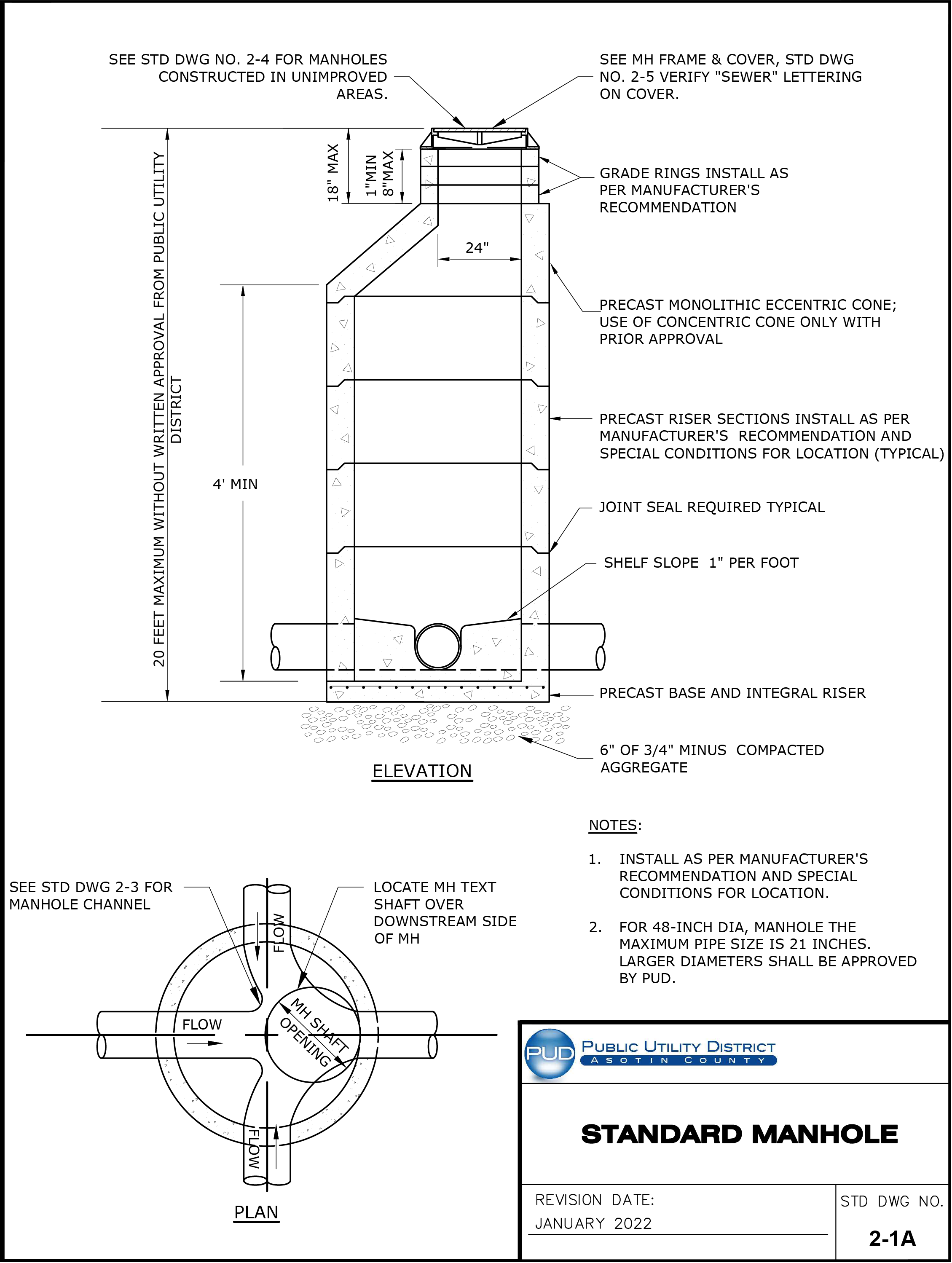
For the original technical drawing, see Construction Standards & Specifications PDF, PDF page 153 of 270.
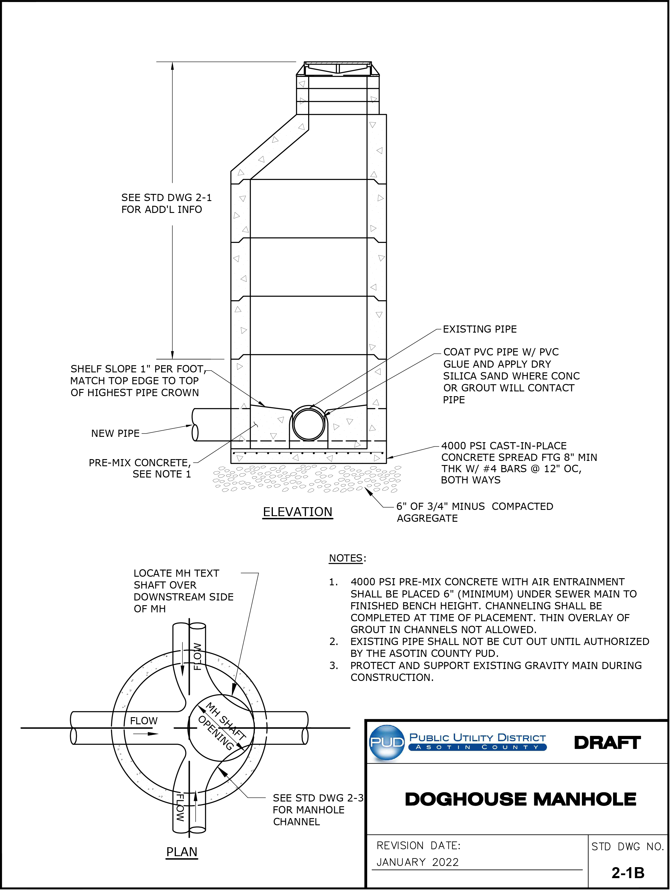
For the original technical drawing, see Construction Standards & Specifications PDF, PDF page 154 of 270.
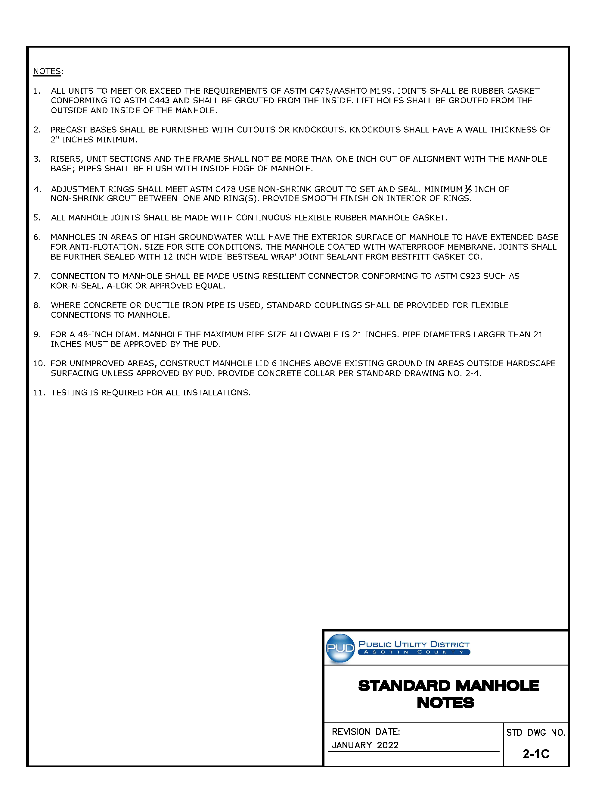
For the original technical drawing, see Construction Standards & Specifications PDF, PDF page 155 of 270.
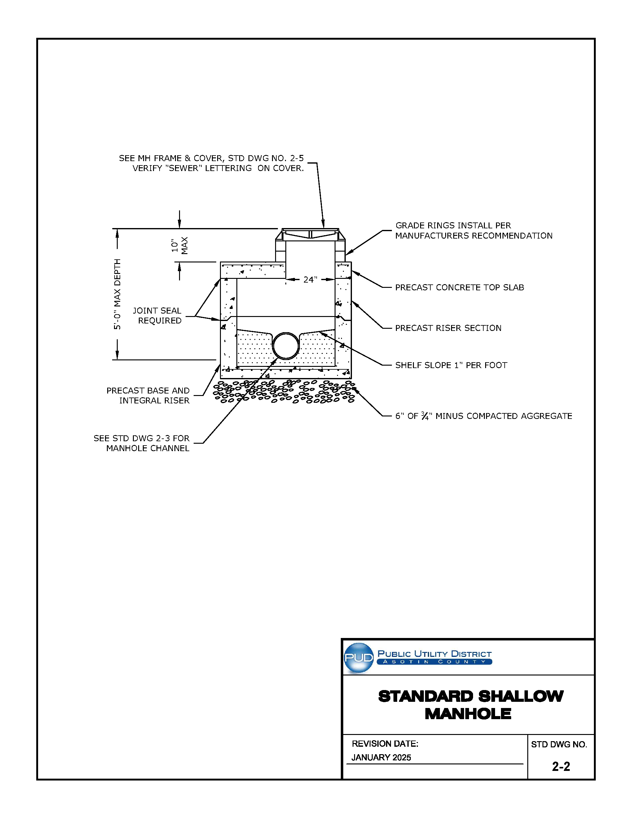
For the original technical drawing, see Construction Standards & Specifications PDF, PDF page 156 of 270.
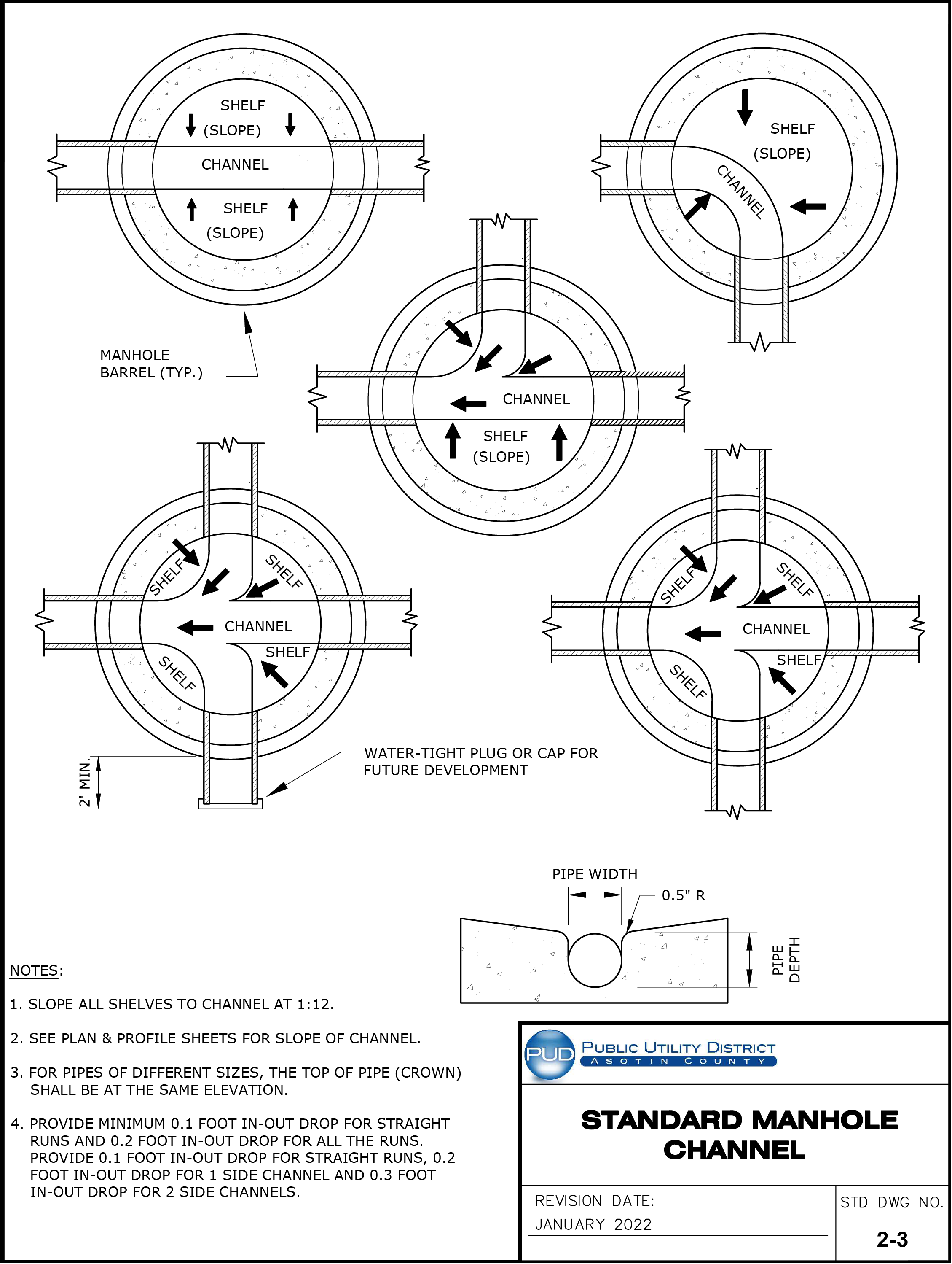
For the original technical drawing, see Construction Standards & Specifications PDF, PDF page 157 of 270.
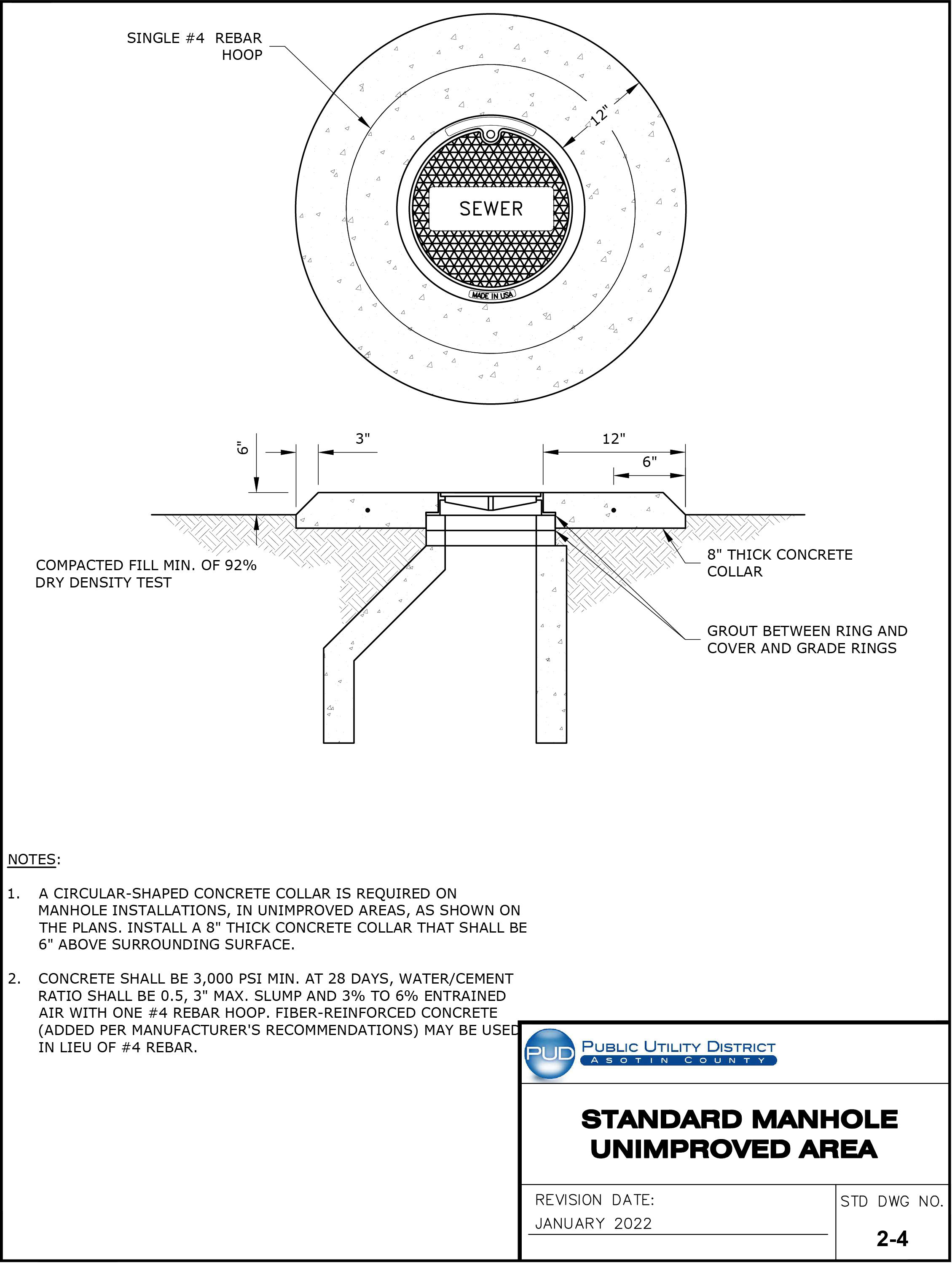
For the original technical drawing, see Construction Standards & Specifications PDF, PDF page 158 of 270.
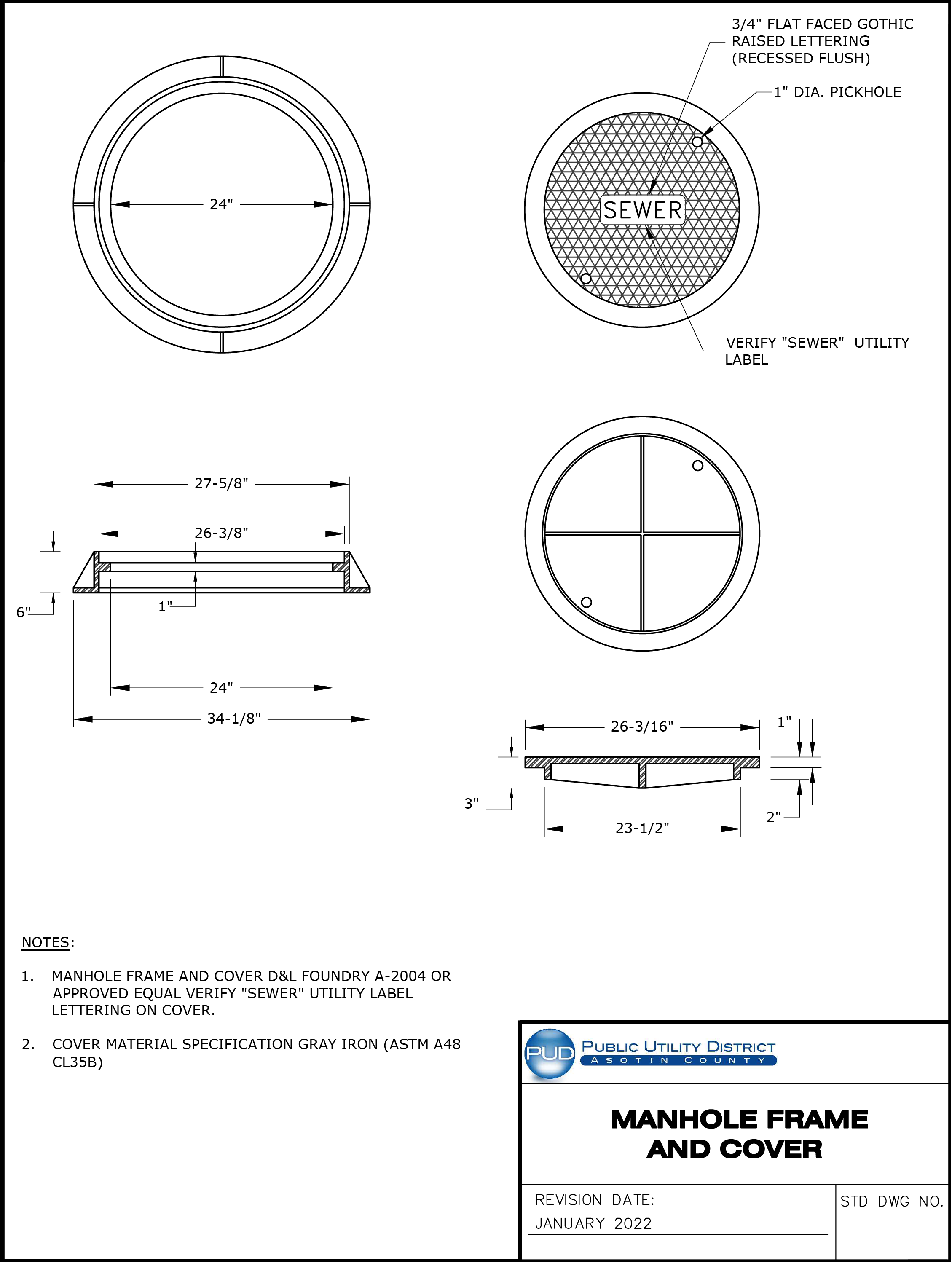
For the original technical drawing, see Construction Standards & Specifications PDF, PDF page 159 of 270.
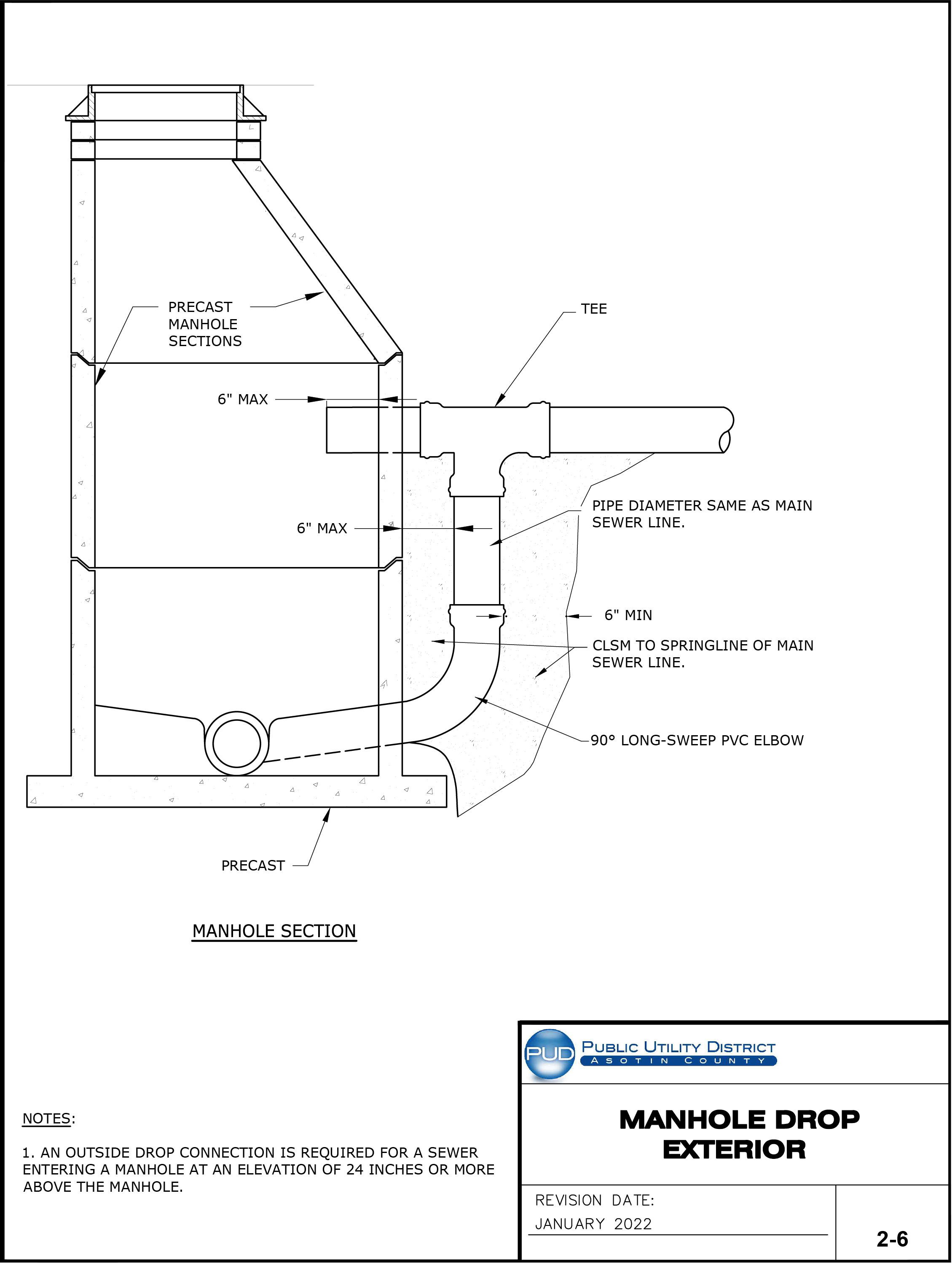
For the original technical drawing, see Construction Standards & Specifications PDF, PDF page 160 of 270.
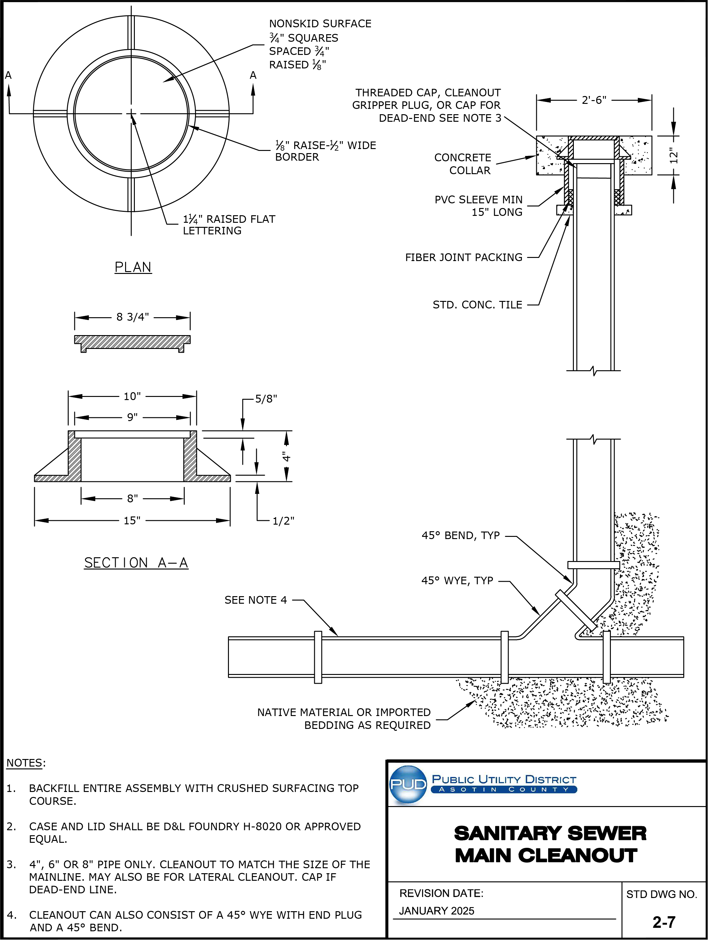
For the original technical drawing, see Construction Standards & Specifications PDF, PDF page 161 of 270.
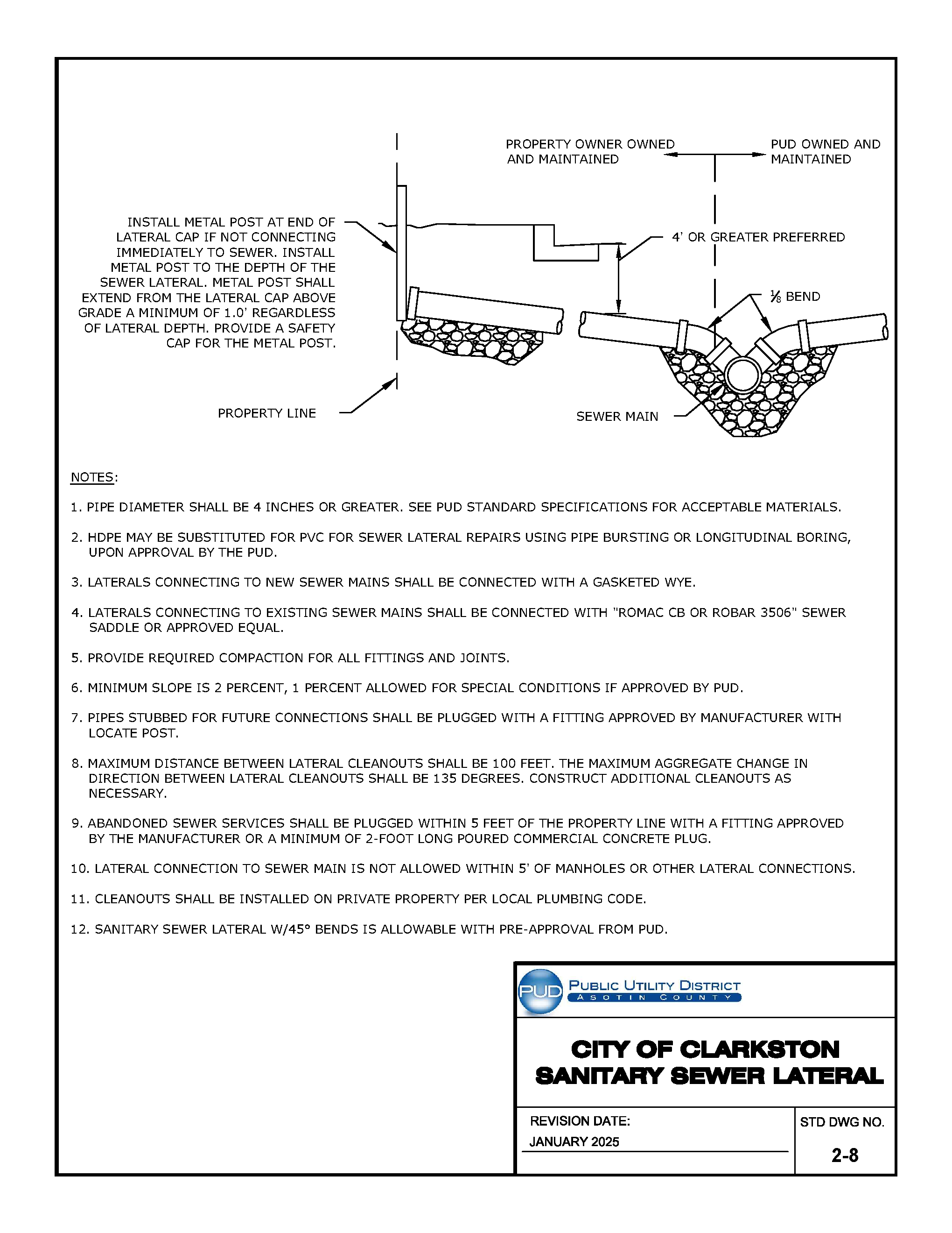
For the original technical drawing, see Construction Standards & Specifications PDF, PDF page 162 of 270.
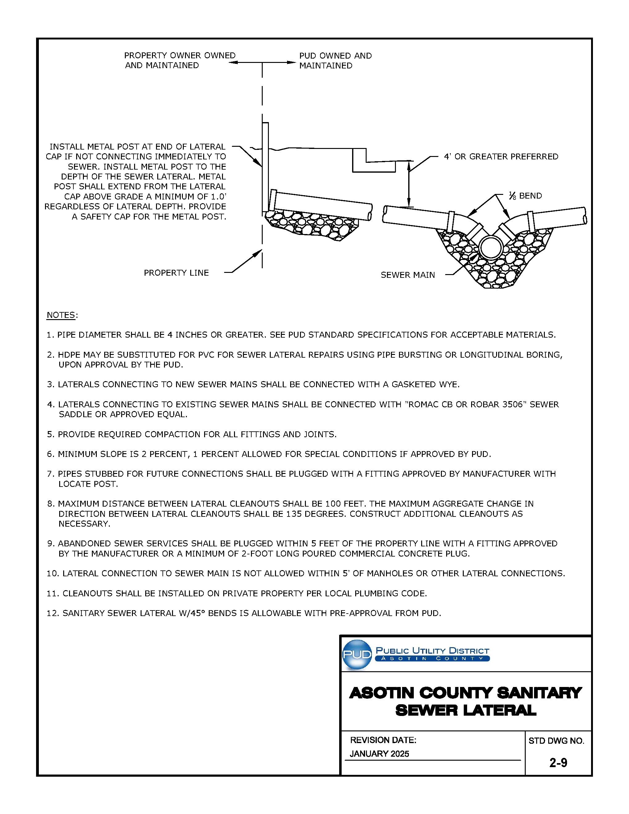
For the original technical drawing, see Construction Standards & Specifications PDF, PDF page 163 of 270.
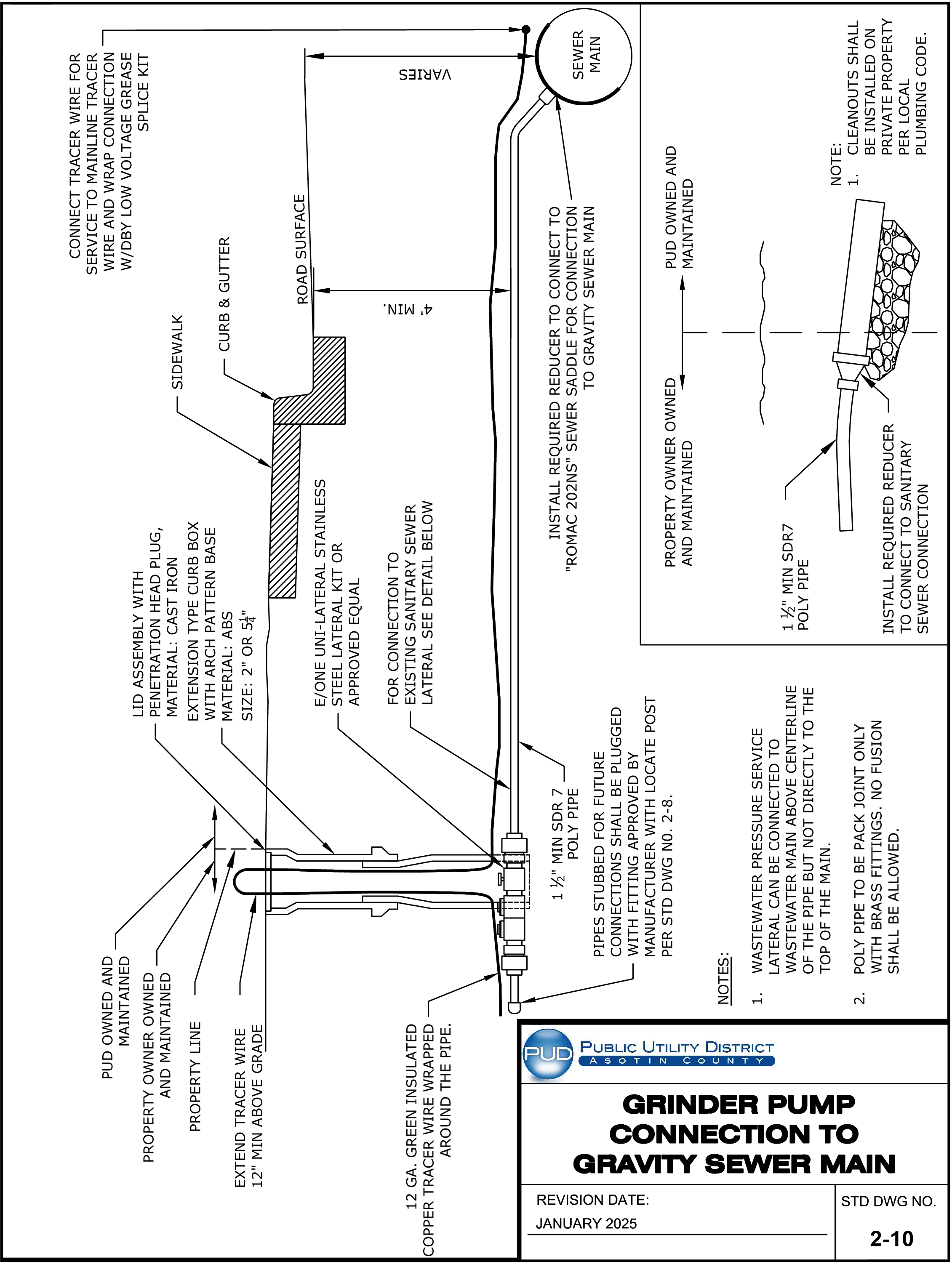
For the original technical drawing, see Construction Standards & Specifications PDF, PDF page 164 of 270.
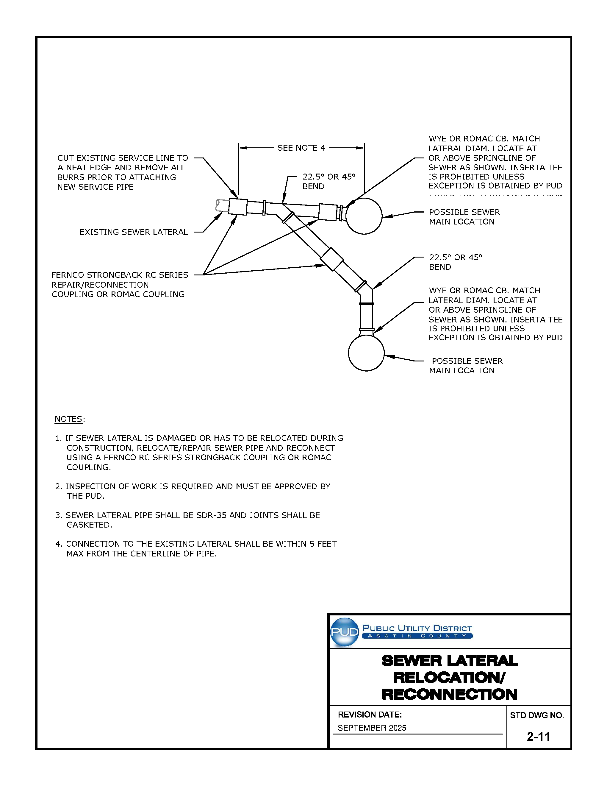
For the original technical drawing, see Construction Standards & Specifications PDF, PDF page 165 of 270.
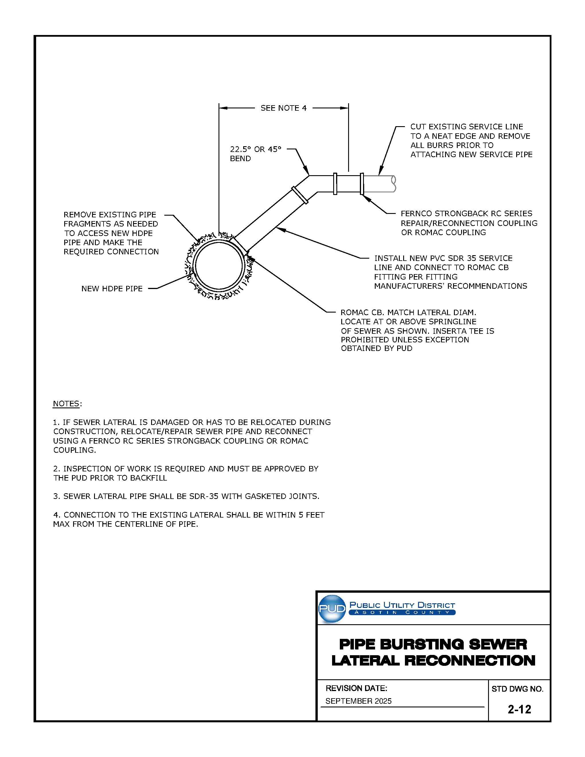
For the original technical drawing, see Construction Standards & Specifications PDF, PDF page 166 of 270.
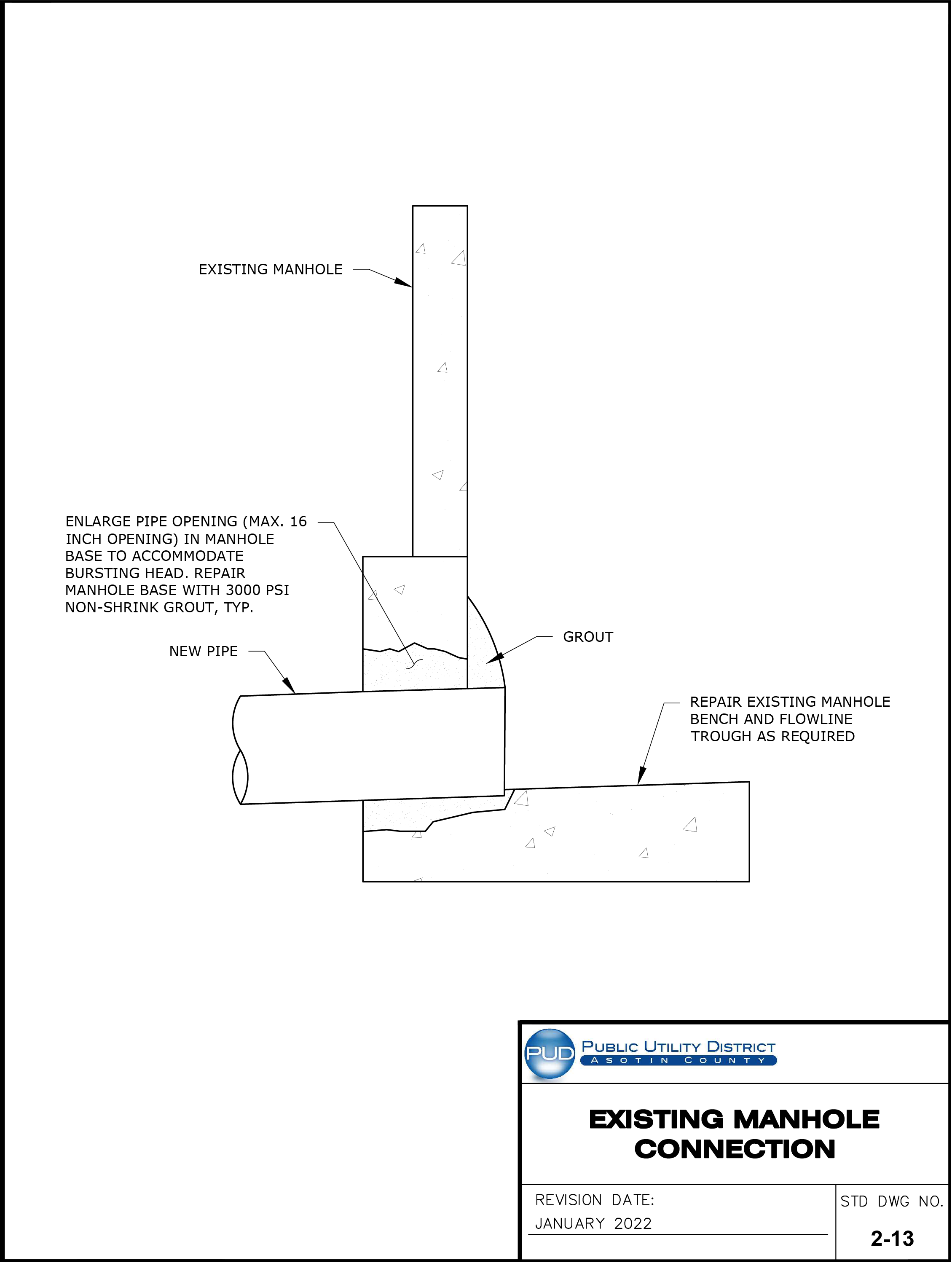
For the original technical drawing, see Construction Standards & Specifications PDF, PDF page 167 of 270.
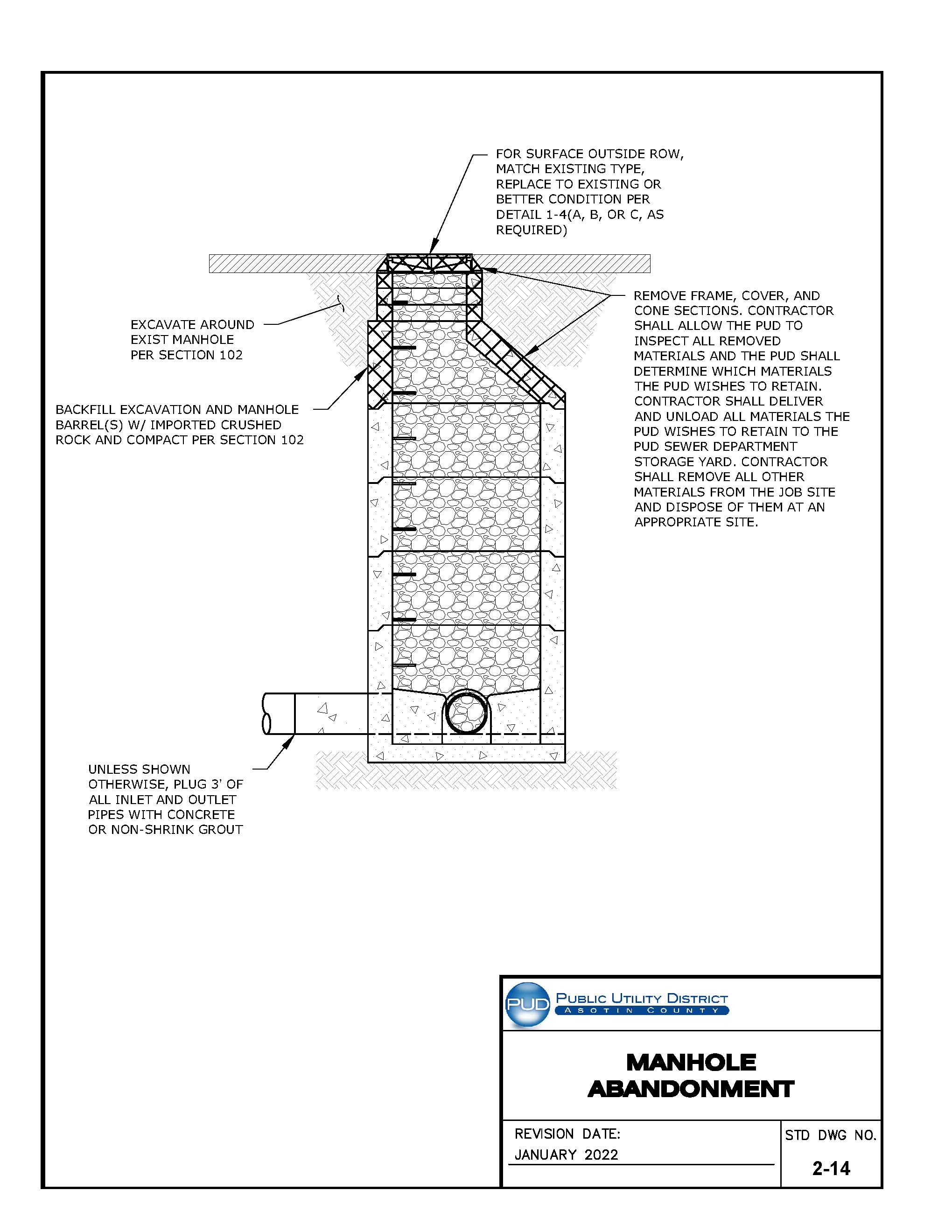
For the original technical drawing, see Construction Standards & Specifications PDF, PDF page 168 of 270.
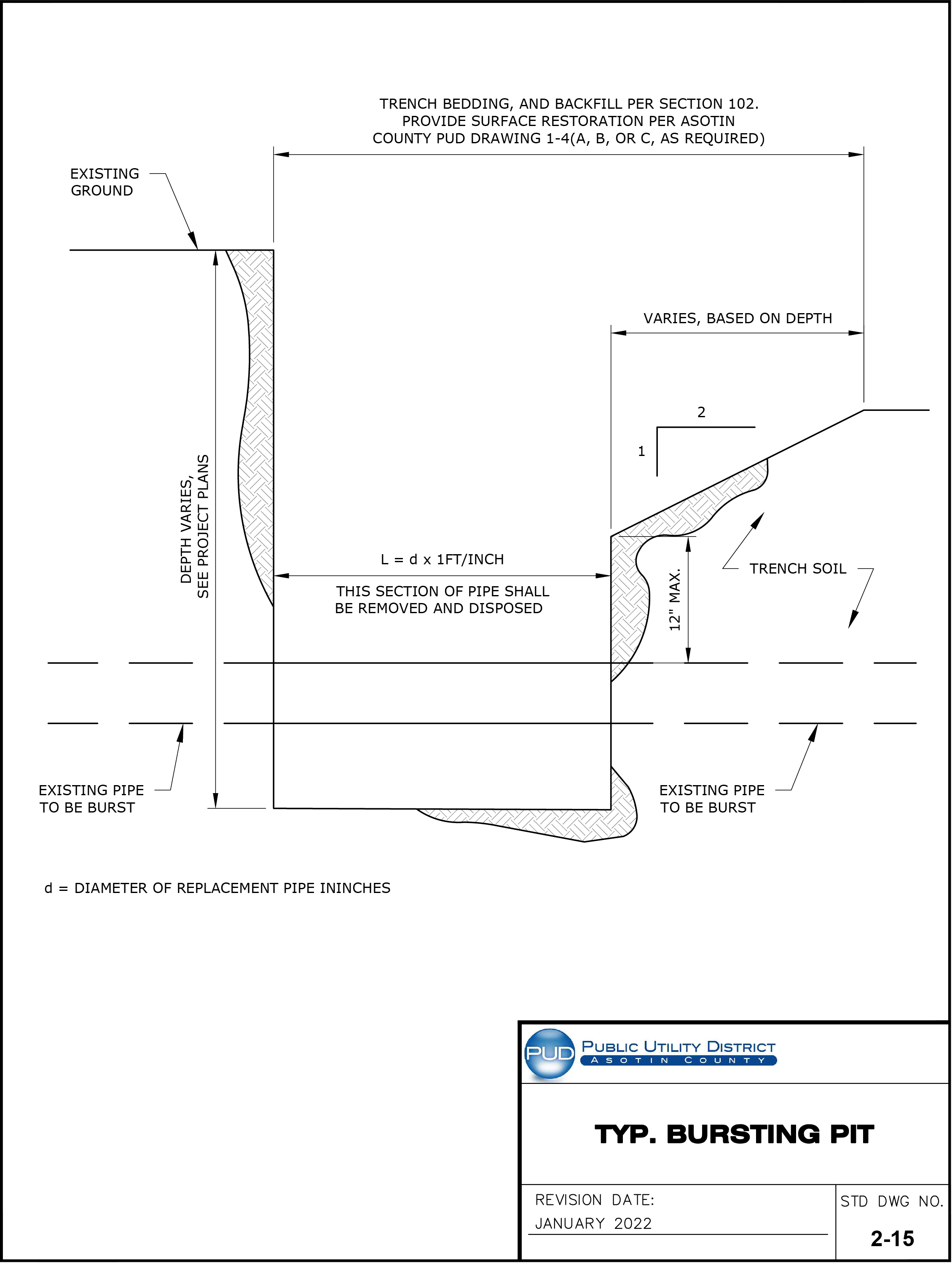
For the original technical drawing, see Construction Standards & Specifications PDF, PDF page 169 of 270.
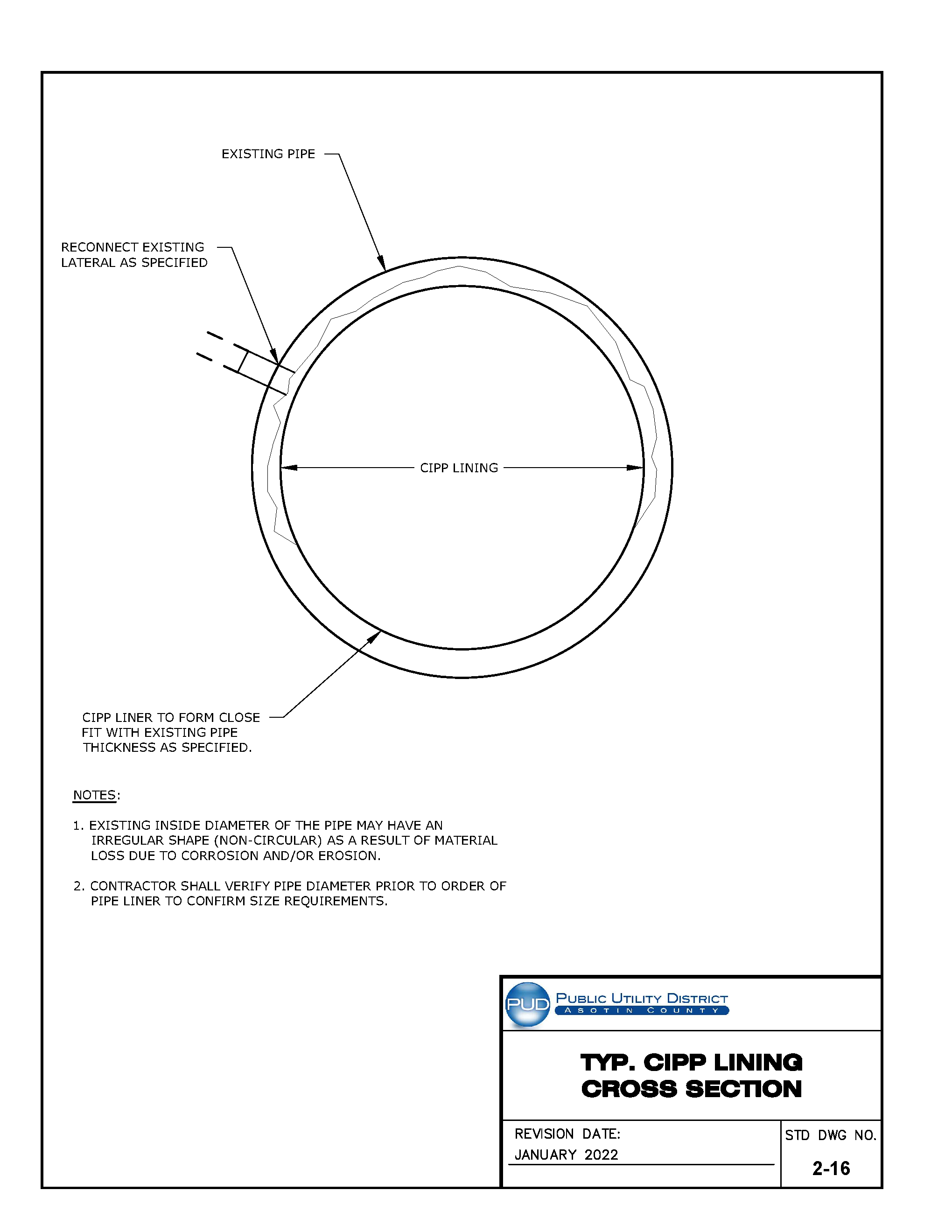
For the original technical drawing, see Construction Standards & Specifications PDF, PDF page 170 of 270.
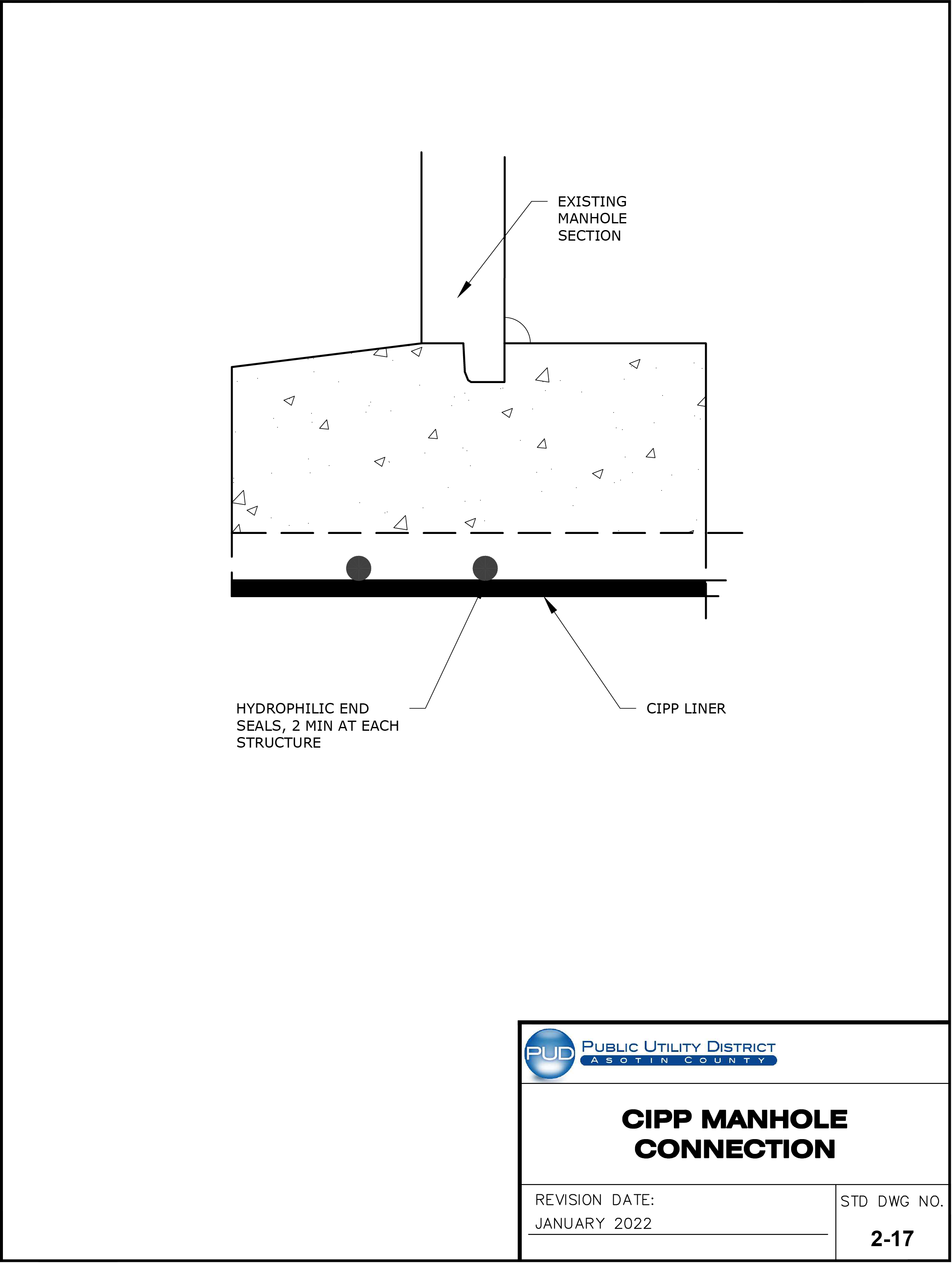
For the original technical drawing, see Construction Standards & Specifications PDF, PDF page 171 of 270.
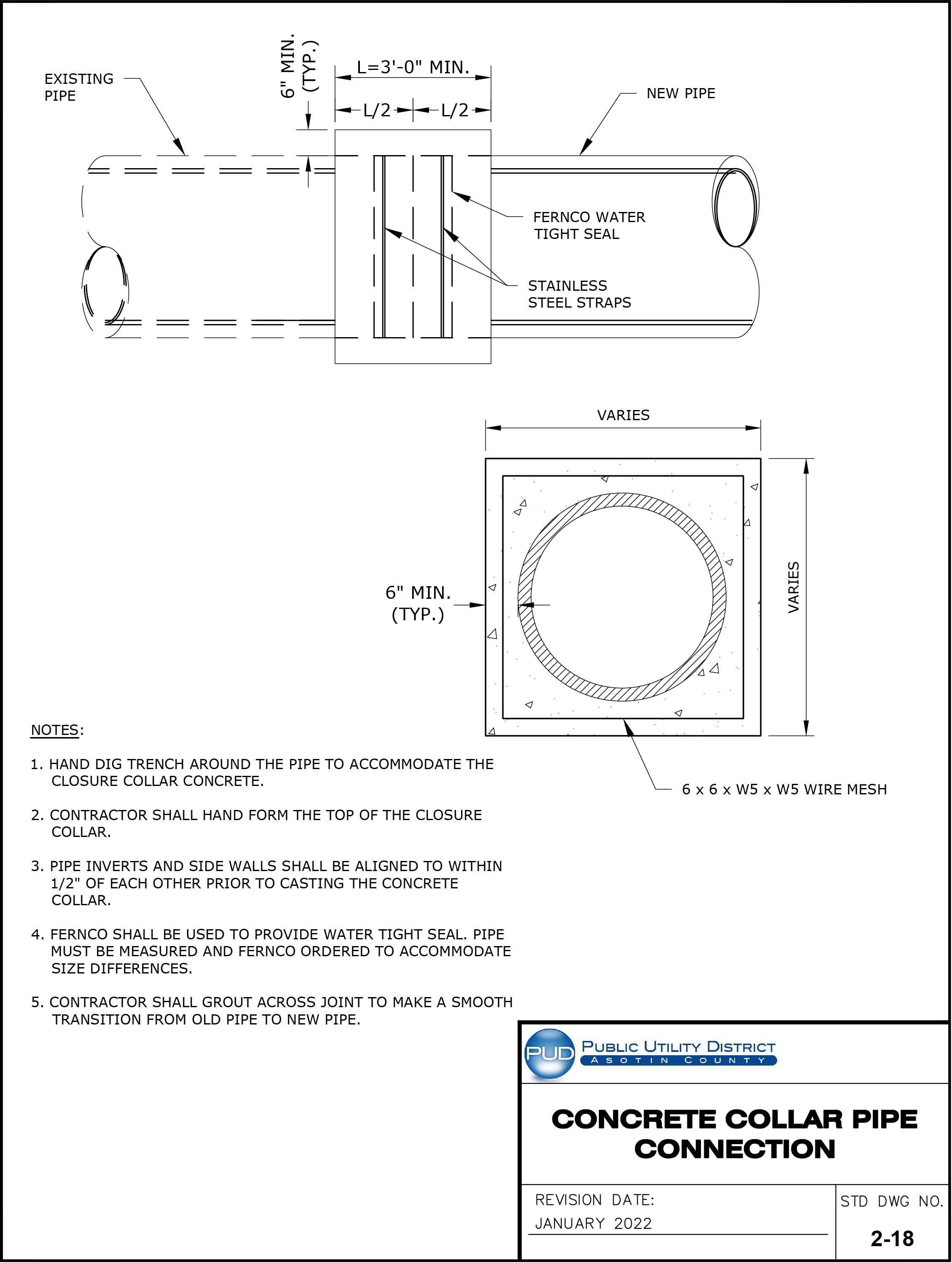
For the original technical drawing, see Construction Standards & Specifications PDF, PDF page 172 of 270.
STANDARD WATER SPECIFICATIONS AND DRAWINGS
FOR
April 2026
CONSOR 300 E Mallard Drive, Suite 350 Boise, ID 83706 208.639.8185
SECTION 300
PIPELINE TESTING AND DISINFECTION
PART 1 GENERAL
1.1 DESCRIPTION
- This section covers field pressure testing, disinfection and purity testing of potable water systems piping, fittings and valves. All piping shall be flushed and hydrostatically pressure and leak tested. Water flowing in pipeline shall be verified to Asotin County PUD. Defective items revealed by the testing procedures shall be removed and replaced or otherwise corrected as directed by the Asotin County PUD. All costs for labor and materials necessary to conduct the flushing, testing and disinfecting procedures specified herein, and all costs of labor and materials required to remedy defective items shall be borne by the CONTRACTOR.
- The CONTRACTOR shall provide 72-hour notification to the Asotin County PUD prior to conducting flushing, hydrostatic testing and disinfection. The CONTRACTOR shall provide coordination and scheduling required for the Asotin County PUD to witness and provide necessary labor for operating the Asotin County PUD’s existing system during hydrostatic testing and disinfecting procedures. The CONTRACTOR shall not operate any part of the existing water system.
- The CONTRACTOR shall perform flushing and testing of all pipelines and appurtenant piping for water or sewage and disinfection of all pipelines and appurtenant piping for potable water, complete, including conveyance of test water to point of use and all disposal thereof, all in accordance with the requirements of the Asotin County PUD and the Standard Specifications and Details.
- Unless otherwise directed by the Asotin County PUD, new water mains and appurtenances must be completely installed, flushed, tested, disinfected, and satisfactory bacteriological sample results received prior to completing permanent connections to existing water system.
1.2 REFERENCE SPECIFICATIONS, CODES AND STANDARDS
Codes and Standards: Comply with the provisions of the latest edition of the following codes, standards and specifications, except as otherwise shown and specified:
- ANSI/AWWA B300 Hypochlorites
- ANSI/AWWA B301 Liquid Chlorine
- ANSI/AWWA C651 Disinfecting Water Mains
- ANSI/AWWA C600 Installation of Ductile-Iron Water Mains and Their Appurtenances
- ANSI/AWWA C605 Underground Installation of PVC Pressure Pipe and Fittings for Water
1.3 CONTRACTOR SUBMITTALS
A pipeline testing and disinfection plan will be required to be submitted by the CONTRACTOR for review and approval by the Asotin County PUD a minimum of one month before testing is to start. As a minimum, the CONTRACTOR’s pipeline testing and disinfection plan shall include the following:
- Testing schedule
- Proposed equipment and chemicals
- Proposed plan for water conveyance including flow rates
- Proposed plan for water control
- Proposed plan for water disposal including flow rates
- Proposed measures to be incorporated in the project to minimize erosion while discharging water from the pipeline
- Proposed plan for disinfection
- Proposed plan for dechlorination including discharge points and discharge rates
- Proposed plan for testing chlorine levels throughout the length of the pipeline including test locations
PART 2 PRODUCTS
2.1 EQUIPMENT
- All test equipment, test forms (found at the end of this Section), chemicals for chlorination, sample bottles, temporary valves, bulkheads, or other water control equipment and materials shall be determined and furnished by the CONTRACTOR subject to the Asotin County PUD’s review. No materials shall be used which would be injurious to the construction or its future functions.
As a minimum, the CONTRACTOR shall furnish the following equipment and materials for the testing:
Amount Description 2 Graduated containers 1 Hydraulic pump with hoses, valves and fittings as needed and required for the testing and disinfection of the facilities. 2 Pressure gauges with pressure range at least 120% greater than the required maximum test pressure with graduations in two (2) psi increments. Gauges shall have been calibrated with 90 days of pressure testing. As Req’d Bacteriological test sample bottles - Chlorine for disinfection shall be in the form of liquid chlorine, sodium hypochlorite solution, or calcium hypochlorite granules or tablets.
- Sodium hypochlorite and calcium hypochlorite shall be in accordance with the requirements of ANSI/AWWA B300. Liquid chlorine shall be in accordance with the requirements of ANSI/AWWA B301.
- Bacteriological test sample bottles shall be obtained from the following facility:
- All temporary thrust restraint and equipment and facilities required for hydrostatic testing will be considered incidental.
PART 3 EXECUTION
3.1 HYDROSTATIC TESTING OF WATER MAINS EXCLUDING HDPE MAINS
- All testing shall be observed by the Asotin County PUD and CONTRACTOR shall document and submit results to the Asotin County PUD within 3 days.
- The CONTRACTOR shall make all necessary provisions for conveying water to the points of use and for the proper disposal of test water.
- No section of the pipeline shall be hydrostatically tested until all field-placed concrete or mortar has attained full strength. At the CONTRACTOR’s option, early strength concrete may be used when the full strength requirements conflict with schedule requirements. All such early applications shall be approved by the Asotin County PUD prior to each installation.
- All piping shall be tested under a hydrostatic test pressure of 150 psi (+/- 5 psi) at the lowest point along the test section or as shown on the plans. If test pressure is greater than 150 psi, CONTRACTOR shall verify with ENGINEER appropriate thrust blocks and restraint is provided. Thrust blocks and restraint in these specifications is based on 150 psi. Testing shall be performed by filling the pipe with potable water from PUD distribution system with approved backflow assembly device or approved potable water truck. Allow for natural absorption to occur and apply the specified test pressure by pumping. Once the test pressure has been attained, the pump shall be valved off. The test will be conducted for one 2-hour period with the allowable leakage not to exceed value as per Paragraph E below.
During the test, pipe, fittings and valves with welded and/or flanged joints shall be completely watertight. Pipe, fittings and valves with rubber gasketed joints (mechanical joints or push-on joints) shall have a measured loss not to exceed the rate given in the following formula:
In the above formula:
Hydrostic Test Allowable Leakage
Diameter (inch) Length (ft) Hydrostatic Test Pressure Allowable Leakage (gallon/hour) 4 100 150 0.03 6 100 150 0.05 8 100 150 0.07 10 100 150 0.08 12 100 150 0.10 14 100 150 0.12 16 100 150 0.13 18 100 150 0.15 20 100 150 0.17 24 100 150 0.20 During the test period, operate the pump as required to maintain pressure in the pipe within 5 psi of the specified test pressure at all times. At the end of test period, operate the pump until the specified test pressure is again obtained. The pump suction shall be in a graduated barrel or similar device or metered so that the amount of water, measured in gallons, required to restore the test pressure may be accurately measured.
- If the test reveals any defects, leakage in excess of the allowable, or failure, the CONTRACTOR shall furnish all labor, equipment and materials required to locate and make necessary repairs. The testing of the line (and repairing of defects, excessive leakage, and failures) shall be repeated until a test satisfactory to the Asotin County PUD has been achieved. All costs for locating, repairing, and retesting shall be borne by the CONTRACTOR.
3.2 HYDROSTATIC TESTING OF HDPE WATER MAINS
- All testing shall be observed by the Asotin County PUD. CONTRACTOR shall document and submit results to the Asotin County PUD within 3 days.
- All HDPE pipe shall be hydrostatically tested twice. The first test shall be conducted above grade after the pipe is butt fused and ready for installation. The second test shall be conducted after the pipe is in place in the trench or, in the case of installation by the horizontal directional drilling method, the pipe has been pulled into place. Prior to conducting the second test, the pipe shall be flushed.
- Before commencing each test, the pipeline shall be filled with potable water from PUD distribution system with approved backflow assembly device or approved potable water truck. Fill pipeline to the specified test pressure and allow to stand without makeup pressure until the pressure reaches equilibrium. Equilibrium will usually occur within 2 to 4 hours. After equilibrium has been reached, the test section shall be returned to the specified test pressure and the test period can begin.
- Hydrostatic test shall be under a hydrostatic test pressure of 150 psi (+/- 5 psi) at the lowest point along the test section or as shown on the plans. If test pressure is greater than 150 psi, CONTRACTOR shall verify with ENGINEER appropriate thrust blocks and restraint is provided. Thrust blocks and restraint in these specifications is based on 150 psi. Testing shall be performed by applying the specified test pressure by pumping. Once the test pressure has been attained, the pump shall be turned off and disconnected from the test section. The test will be conducted for one two-hour period in accordance with Paragraph 3.1.F above with the allowable leakage not to exceed the value as per Paragraph 3.1.E above.
- During the above-grade test, the pipe shall be visually inspected for leaks. All leaks shall be repaired before installing the pipe in the trench or pulling the pipeline into the borehole. Leaks at fusion joints shall be repaired by cutting out the leaking fusion joint, re-fusing the joint and conducting a new above-grade test.
The second pressure test shall be made after the first pressure test has been successfully completed and approved by the Asotin County PUD and the HDPE pipeline is installed. For HDPE pipe installed by the horizontal directional drilling method, the test section shall be the full length of pipeline that is pulled into place.
After the equilibrium period specified in Paragraph 3.2.C above, the pressure test shall proceed as specified in Paragraph 3.2.D above for a period of two (2) hours. Leakage shall not exceed that specified in Paragraph 3.1.E above. If the test fails, the installed pipe section shall be removed and replaced with new HDPE pipe.
- The CONTRACTOR shall schedule pressure testing such that pressure changes due to thermal expansion or contraction of the pipe during the test period are minimized.
- If the testing reveals any defects, any leakage, or any failure, the CONTRACTOR shall furnish all labor, equipment and materials required to locate and make necessary repairs. The testing of the line and repairing of defects, excessive leakage, and failures shall be repeated until a test satisfactory to the Asotin County PUD has been achieved. All costs for locating, repairing, and retesting shall be borne by the CONTRACTOR.
3.3 DISINFECTION OF WATER MAINS
- After testing and repairing where necessary, all potable water systems shall be thoroughly flushed, cleaned, and disinfected by the CONTRACTOR in accordance with the latest version of AWWA C651. Chlorination by means of tablets (calcium hypochlorite) placed in each length of pipe during installation is specifically prohibited. Chlorination by means of powder (calcium hypochlorite) placed in each length of pipe during installation is acceptable.
- Before sterilizing, flush all foreign matter from the pipeline. The CONTRACTOR is to provide, at no additional cost to the Asotin County PUD, hoses, temporary pipes, ditches, etc., as required to dispose of flushing water without damage to adjacent properties. Flushing velocities shall be at least 2.5 fps. For large diameter pipe where it is impractical or impossible to flush the pipe at 2.5 fps velocity, clean the pipe in place from the inside by brushing and sweeping, then flush the line at a lower velocity.
- Potable water piping shall be disinfected with a solution containing a minimum 25 parts per million (ppm) and a maximum 50 ppm of chlorine. The chlorine solution shall remain in the piping system for a period of 24 hours at which time the sterilizing mixture shall have a strength of at least 10 ppm of chlorine. If check samples fail to produce acceptable results, the disinfection procedure shall be repeated at the expense of the CONTRACTOR until satisfactory results are obtained.
- Disposal of any water containing chlorine shall be performed in accordance with the latest edition of AWWA C651, and any other state or local requirements. Disposal may be made into existing sanitary sewer systems providing approvals are obtained from Asotin County PUD. Chlorinated water may not be discharged to open stream channels or stormwater systems.
- The CONTRACTOR shall collect samples after the pipeline is flushed in accordance with the latest edition of AWWA C651. The chlorine residual must be below 1.5 mg/L when the sample is taken. Two consecutive sets of acceptable samples, taken at least 24 hours apart, shall be collected from the new main. At least one set of samples shall be collected from every 1,200 feet (366 m) of the new water main, plus one set from the end of the line and at least one set from each branch. Chlorine residual testing results and samples shall be reviewed and approved by the Asotin County PUD.
- Results of the bacteriological testing shall be submitted within 2 days of testing and be satisfactory with the Asotin County PUD and the State Department of Health and/or other appropriate regulatory agencies, or disinfection shall be repeated at the expense of the CONTRACTOR.
3.4 DISINFECTION OF WATER MAIN END CONNECTIONS AND TIE-INS
Disinfection and pressure testing of potable water piping and appurtenances at end connections which are required to remain in service due to restrictions in allowable shutdown time shall be pressure tested and disinfected as described below:
- Prior to connecting new potable water piping and appurtenances with existing piping and appurtenances, the interior of all new pipe, fittings, valves and appurtenances shall be swabbed or sprayed with a 1% to 5% calcium hypochlorite solution. Swabbing or spraying connecting piping is acceptable for a maximum of length of 18 feet.
- Following the disinfection procedure described above, connection of the new piping and appurtenances to the existing water system shall be made. During the system startup, the Asotin County PUD and CONTRACTOR shall visually inspect all new fittings, piping, valves and appurtenances for evidence of leakage. Any leakage observed during this period shall be promptly repaired by the CONTRACTOR, at the CONTRACTOR’s expense as required by the Asotin County PUD.
3.5 HYDROSTATIC TESTING OF WATER SERVICE CONNECTIONS
- Service Lines shall be flushed prior to hydrostatic testing service laterals. Water flowing from each service shall be verified to the Asotin County PUD prior to testing. This requirement is applicable only for newly installed service lines and is not required for the replacement of existing water service lines.
3.6 HYDROSTATIC TESTING OF FIRE SERVICE CONNECTIONS
Service lines serving fire services or sprinkler systems shall not be hydrostatically tested against water system or shut water system valve. CONTRACTOR to provide valve or caps to service line for duration of test. CONTRACTOR to provide any restraint or thrust blocks required for test. Testing shall be inspected and observed by local Fire Marshall.
HYDROSTATIC PRESSURE TEST RECORD FORM
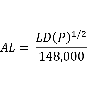
For the original technical form, see Construction Standards & Specifications PDF, PDF page 183 of 270.
| Date: Time: | Project: Client: City: | Report #: |
|---|---|---|
| Technician: | Inspector: | Weather: |
| From: Street: | ||
| To: Street: | ||
| Pipeline Data | |||
|---|---|---|---|
| Pipe Diam. (in): | |||
| Length (ft): | |||
| Pipe Material: | |||
| Test Data | |||
| Pressure Gauge: | Type: | Range: | Calibration Date: |
| Required Test Pressure: | Allowable Leakage: | ||
| Test Start Time: | Test End Time: | ||
| Test Duration (ending – starting time): | |||
| Actual Test Pressure: | |||
| Actual Leakage: | |||
| Results | |||
| Comments: | |||
| Inspection: | ☐ Satisfactory ☐ Unsatisfactory | ||
| Pressure Test: | ☐ Satisfactory ☐ Unsatisfactory | ||
| Operator Performing Work | Print: | Signature: | Date: |
| Inspector Witnessing Test: | Print: | Signature: | Date: |
END OF SECTION
SECTION 301
DUCTILE IRON PIPE, FITTINGS AND SPECIAL ITEMS
PART 1 GENERAL
1.1 DESCRIPTION
- Work under this Section applies to the furnishing and installation of ductile iron pipe, fittings and special items for buried service. The CONTRACTOR shall furnish and install ductile iron pipe, fittings, valves, special items and all appurtenant work, complete in place, all in accordance with the requirements of the Standard Specifications and Drawings.
1.2 REFERENCE SPECIFICATIONS, CODES AND STANDARDS
- Commercial Standards
| 1. ANSI B16.1 Fittings, Class 25, 125, 250, and 800 | Cast Iron Pipe Flanges and Flanged |
|---|---|
| 2. ANSI/NSF Standard 61 | Drinking Water System Components |
| 3. ASTM A126 Valves, Flanges, and Pipe Fittings | Specification for Gray Iron Castings for |
| 4. ANSI/AWWA C104/A21.4 Pipe and Fittings | Cement-Mortar Lining for Ductile-Iron |
| 5. AWWA C105 Pipe Systems | Polyethylene Encasement for Ductile-Iron |
| 6. ANSI/AWWA C110/21.10 | Ductile-Iron and Gray-Iron Fittings |
| 7. ANSI/AWWA C111/A21.11 Pressure Pipe and Fittings | Rubber-Gasket Joints for Ductile-Iron |
| 8. ANSI/AWWA C115/A21.15 Iron or Gray-Iron Threaded Flanges | Flanged Ductile-Iron Pipe with Ductile- |
| 9. ANSI/AWWA C150/A21.50 | Thickness Design of Ductile-Iron Pipe |
| 10. ANSI/AWWA C151/A21.51 | Ductile-Iron Pipe, Centrifugally Cast |
| 11. ANSI/AWWA C153/A21.53 Service | Ductile-Iron Compact Fittings for Water |
| 12. AWWA C600 and Their Appurtenances | Installation of Ductile-Iron Water Mains |
1.3 SUBMITTALS
- Product technical data and material data; including all pipe, fittings, restrained joint systems, and appurtenance information.
- Lining and coating data.
- Applicable material certifications and testing certificates.
- Manufacturer's handling delivery storage and installation requirements.
- Documentation of tracer wire continuity tests
1.4 QUALITY ASSURANCE
- Unless otherwise noted, all water works materials provided for the project shall be new, of first class quality and shall be made by reputable manufacturers. All material of a like kind shall be provided from a single manufacturer unless otherwise approved by the Asotin County PUD. All material shall be carefully handled and installed in good working order free from defect in manufacture, storage and handling. Where an item is to be used but does not have its quality specified herein, it shall be equal to that specified in the appropriate American Water Works Association (AWWA) Standard Specification.
- All references to standards of AWWA or other organizations shall be the latest versions of those standards.
PART 2 PRODUCTS
2.1 GENERAL
- Ductile iron piping materials and specials shall meet the specifications of this Section and of the appropriate AWWA Standard Specifications. In the case of conflict, the more stringent specifications shall apply.
- Unless otherwise specified herein or shown on the plans, the minimum working pressure rating of all water works material specified herein shall be 1.5 times the operating pressure or 150 psi minimum.
- All coatings and materials specified herein that come in contact with potable water shall be National Sanitation Foundation (NSF) approved.
2.2 DUCTILE IRON PIPE
Ductile iron pipe shall conform to AWWA Standard C151 and shall be the standard push-on joint type or restrained joint type as identified on the drawings. Push-on joints shall be “TYTON” type or “Fas-Tite” type without exception. Unless otherwise specified herein or shown on the plans, ductile iron pipe shall be thickness Class 52. Polyethylene encasement, where required on the drawings or specified elsewhere, shall conform to AWWA Standard C105.
- All ductile iron pipe 24 inches in diameter or greater shall be fully gauged for the last 2 feet of each spigot end and shall meet the outside diameter standard dimensions and tolerances required for spigot ends along the last 2 feet of each pipe piece. Pipe shall be externally marked, in manufacturer’s color, indicating gauged pipe. Where piping is to be cut, such pipes shall be fully gauged and shall meet the outside diameter standard dimensions and tolerances required for spigot ends long the entire length of pipe. A minimum of 30% of each size of piping greater than 24 inches in diameter provided for the project shall by fully gauged for the entire length of each pipe as described above.
- Ductile iron pipe shall be cement mortar lined, interior and exterior sealed in accordance with ANSI/AWWA C104.A21.4.
- Push-on or mechanical type pipe joints shall conform to AWWA Standard C111. Flanged ductile iron pipe shall conform to AWWA Standard C115.
Restrained Joint Ductile Iron Pipe
- Restrained joint ductile iron pipe and fittings shall be provided as identified on the drawings and required for the application. Joint restraint for pipe shall be accomplished with an integral lock mechanism except as may be otherwise specified. Any such system shall be a manufacturer's standard proprietary design, shall be as recommended by the manufacturer for the application, and shall be performance proven.
- Restraining components for pipe shall be ductile iron in accordance with applicable requirements of ANSI/AWWA C110/A21.10 and/or C153/A21.53 with the exception of the manufacturer's proprietary design dimensions. Push-on joints for such fittings shall be in accordance with ANSI/AWWA C111/A21.11.
The following is the approved list of restrained joint systems:
- “Thrust-Lock” Pacific States Cast Iron Pipe Company.
- “Fast Grip” American Cast Iron Pipe Company.
- “TR Flex” United States Pipe and Foundry Company.
- “Snap-Lok” Griffin Pipe Products Company.
- “Megalug” EBAA Iron, Inc.
- “Field-Lok” United States Pipe and Foundry Company.
- “Super Lock” Clow
- “Restrained Joint” McWane
- “MJ-TJ” pipe with “Megalugs” Pacific States Cast Iron Pipe Company.
- “Flex-Ring” American Cast Iron Pipe Company
- Where such a system may require "Mega-Lugs" for restraint, "Mega-Lugs" shall be provided in quantities as may be required and shall be considered incidental to the joint restraint system. Restrained piping shall be pressurized following installation and prior to completing piping tie-ins.
- Restrained joints for pipe shall be designed for a water working pressure as shown on the Drawings.
Joint restraint is required at all mechanical joint fittings and where specified on the plans. Joint restraint at mechanical joint fittings shall be accomplished with the following systems or approved equal:
- 4- to 12-inch pipe: GripRing Pipe Restrainer, as manufactured by Romac Industries, Inc.
- 14-inch pipe and greater: 470 Series Pipe Restraining System, as manufactured by Romac Industries, Inc.
- Ductile iron pipe may be deflected both horizontally and vertically at the joints after assembly. The maximum pipe deflection shall not exceed one half of the manufacturer’s stated joint deflection allowance.
2.3 FITTINGS AND SPECIALS
A. Fittings
- Fittings used for joining ductile iron pipe shall be of the type, size and strength designated on the plans, elsewhere in the specifications, or in the proposal and, to the extent therein specified, shall conform to the appropriate specification in this section. Fittings shall have pressure ratings as specified above and as shown on the plans.
- Fittings shall be mortar lined and seal coated. Mortar lining of fittings shall be factory installed only, unless otherwise directed by Asotin County PUD. All fitting lining interior surfaces shall be smooth finished.
- Pipe fittings and specials used with ductile iron pipe shall be gray-iron or ductile iron and shall conform to AWWA Standard C110. Ductile iron (compact) fittings conforming to AWWA Standard C153 may be substituted in lieu of AWWA C110 fittings for fitting sizes 3 inches through 24 inches in diameter. Fittings shall be mechanical joint, push-on type, flanged or plain-end as required and shown on the plans. When fitting joints are to be restrained, pipe joint restraint systems as specified herein shall be used.
Joint restraint is required at all mechanical joint fittings and where specified on the plans. Joint restraint at mechanical joint fittings shall be accomplished with the following systems or approved equal:
- 4- to 12-inch pipe: GripRing Pipe Restrainer, as manufactured by Romac Industries, Inc.
- 14-inch pipe and greater: 470 Series Pipe Restraining System, as manufactured by Romac Industries, Inc.
B. Flanges
- Threaded flanges shall meet the requirement of AWWA Standard C115 and shall be installed only on pipe with a minimum Class 53 wall thickness. All flanged fittings shall be provided with bolts and gaskets as specified herein. Flanges shall have flat faces and shall be attached with bolt holes straddling the vertical axis of the pipe unless otherwise shown. CONTRACTOR shall coordinate with pipe, valve and fitting suppliers to make certain that pipe, valve and fitting flanges match in bolt pattern.
C. Gaskets
Gaskets for flanged joints shall be as follows:
- Pipe sizes up to 24-inch in diameter: Gaskets shall be full-face gaskets, premium red rubber, 1/8 inch thickness, Garlock 22, or equal.
- Pipe sizes 24-inch and greater: Gaskets shall be ring gaskets, premium red rubber, 1/8-inch thickness, Garlock 22, or equal.
D. Bolts and Nuts
- Bolts and nuts shall be carbon steel and shall conform to the requirements of ASTM A307 or ASTM A193 grade B7 with ASTM A194 grade 2H heavy hex nuts.
E. Flexible Couplings
- All flexible couplings shall be cast or ductile iron in accordance with ASTM Standard A536 and high strength alloy bolts and nuts conforming to ANSI/AWWA C111.
- Insulating flexible couplings shall be of the gasketed sleeve type with insulating boot and shall be Romac Industries, Inc. MACRO or ALPHA as shown on the Plans. All coupling materials shall be constructed to diameters that properly fit the pipe.
- Insulating boot shall be fabricated from nitrile butadiene rubber suitable for water service with electric insulating properties in accordance with ASTM D2000 3 BA 715.
- CONTRACTOR is responsible for selecting sleeve lengths appropriate to application, recognizing longer sleeves allow larger deflections and may ease installation.
F. Insulating Flanged Joints
- Each complete insulating flange kit shall include a full faced gasket, a full-length pyrox insulating sleeve for each flange bolt and two pyrox insulating washers and two steel washers for each bolt. Gaskets shall be Garlock Style 3000 or equal.
G. Flexible Expansion Joints
- Flexible expansion joints shall be installed in the locations indicated on the Drawings and shall be manufactured of ductile iron conforming to the material properties of ANSI/AWWA C153/A21.53. Flexible joints shall be provided with end connections as shown on the Plans. All flexible expansion joints shall consist of an expansion joint designed and cast as an integral part of a ball and socket type flexible joint, having a minimum of 15 degree deflection per ball and 4-inch expansion. Actual expansion and deflection requirements will be as shown on the Drawings. Each flexible expansion joint shall be hydrostatically tested to the manufacturer’s published pressure rating prior to shipment. All pressure containing parts shall be lined with a minimum of 15 mils of fusion bonded epoxy conforming to the applicable requirements of ANSI/AWWA C213 and shall be holiday tested with a 1,500 volt spark test conforming to said specification. All flexible-expansion joints shall be Flex-Tend as manufactured by EBAA Iron, Inc. or approved equal.
H. Tapping Sleeves
- Tapping sleeves shall be stainless steel conforming to 18-8 Type 304 stainless steel with stainless steel flanged end with ANSI 150 lb drilling. Bolts and hardware to be Type 304 stainless steel and the branch outlet shall be heavy stainless steel pipe. The gasket shall be full circumferential gasket. Tapping sleeve shall be Romac SST or approved equal. Tapping sleeve shall be lubed with pipe soap prior to installation.
- Valve for tapping sleeve shall be cast iron body with fusion bonded epoxy coating. Valves shall be as specified in Sections 320, 321, 322, and 323.
I. Tracer Wire
- Tracer wire shall be 12 gauge single strand copper insulated high molecular weight polyethylene (HMWPE) wire. The HMWPE insulated cover shall be blue and shall have a minimum thickness of 45 mils. The wire shall be UL rated for 1400 F.
J. Marking Tape
- Marking tape shall consist of inert polyethylene plastic that is impervious to all known alkalis, acids, chemical reagents and solvents likely to be encountered in the soil. The tape shall be 3-4 inches in width and installed 1 foot above water main. The tape shall be blue and shall be imprinted continuously over its entire length in permanent black ink with the words “Caution Buried Water Line Below”
PART 3 EXECUTION
3.1 GENERAL
- All materials, workmanship and installation shall conform to referenced AWWA Standards and other requirements of these specifications. The methods employed by the CONTRACTOR in the storage, handling, and installation of pipe, fittings, valves, hydrants, equipment and appurtenances shall be such as to ensure that the material, after it is placed, tested and permanently covered by backfilling is in as good a condition as when it was shipped from the manufacturer's plant. Should any damage occur to the material, repairs or replacement shall be made to the satisfaction of the Asotin County PUD.
- Ductile iron pipe shall be installed in accordance with AWWA Standard C600, except as modified elsewhere in these specifications.
- Sanitary Sewer Separation: The CONTRACTOR shall furnish all labor, equipment and materials required to replace sections of existing sanitary sewers or encase existing sanitary sewers in reinforced concrete as required to comply with Washington State Department of Health requirements for minimum separation of sanitary sewers. See also Section 102 - Excavating, Backfilling, and Compacting for Utilities.
3.2 PRODUCT HANDLING
- Care shall be taken in handling and transporting to avoid damaging pipes and their coatings. Loading and unloading shall be accomplished with the pipe under control at all times and under no circumstances shall the pipe be dropped. Pipe shall be securely wedged and restrained during transportation and supported on blocks when stored in the shop or field.
3.3 INSPECTION
- All pipe sections, specials, and jointing materials shall be carefully examined for defects and no piece shall be laid that is known to be defective. Gouges greater than or equal to 10% of pipe wall thickness shall be considered defective. Any defective piece installed shall be removed and replaced with a new pipe section in a manner satisfactory to the Asotin County PUD at the CONTRACTOR’s expense.
- Asotin County PUD shall be allowed to identify and determine if material is defective. Defective material shall be marked with black spray paint and removed from the job site before the end of the day.
3.4 SURVEY LINE AND GRADE AND SURVEY MONUMENT REPLACEMENT
- Refer to Section 102 – Excavating, Backfilling, and Compacting for Utilities, Part 3.2.
3.5 PREPARATION
- Excavate trenches and prepare and maintain subgrade as described in these Specifications and shown on the Plans. Trench base shall be inspected prior to placement of the pipe. Remove large stones or other hard matter which could damage pipe or impede consistent pipe bedding backfilling or compaction.
- All pipe trenches shall be excavated below the proposed pipe invert as shown on the Plans to accommodate the depths of pipe bedding material as scheduled on the Drawings.
Pipe cuts made with proper pipe cutting equipment shall be in accordance with the manufacture’s recommendation. When required to re-bevel a pipe end for proper installation, the contractor shall utilize manufacture recommended bevel angle for the intended use.
- Prior to assembly of field cut pipe, the reference mark shall be re-established with a permanent black marker. The location of the reference mark at the proper distance from the bevel end shall be in accordance with the manufacturer’s recommendations.
Pipe Cleaning
- each section of the pipe and each fitting shall be thoroughly cleaned before it is lowered into the trench. Cleaning of each pipe or fitting shall be accomplished by swabbing out, brushing out, blowing out with compressed air, or washing to remove all foreign matter.
- If clean pipe sections and fittings cannot be placed in the trench without getting dirt into the open ends, the Asotin County PUD may require that a piece of tightly woven canvas be tied over the ends of the pipe and/or fitting until it has been lowered into position in the trench. After the pipe and/or fitting has been lowered into the trench, all foreign matter shall be completely brushed from the bell and spigot ends before assembly.
3.6 INSTALLATION
- Install pipe and accessories in accordance with these specifications and the manufacturer’s instructions.
- Lift or roll pipe into position. Do not drop or drag pipe over prepared bedding.
Joints
- Pipe jointing surfaces shall be clean and dry when preparing surfaces for joining. Lubricants, primers, adhesives, etc. shall be used as recommended by the pipe or joint manufacturer’s specifications. The jointing materials or factory-fabricated joints shall then be placed, fitted, joined and adjusted in such a manner as to obtain a watertight joint. Trenches shall be kept water-free and as dry as possible during bedding, laying and jointing. As soon as possible after the joint is made, sufficient backfill material shall be placed along each side of the pipe to prevent movement of the pipe from any cause.
Water Main Hot Tapping
- The CONTRACTOR shall furnish all tools and materials required for a complete installation including necessary testing.
- The CONTRACTOR shall verify existing water main outside diameter size and material. CONTRACTOR shall contact Asotin County PUD prior to any excavation.
- The CONTRACTOR shall schedule water main tap with Asotin County PUD 72 hours prior to installation date. CONTRACTOR shall excavate water main prior to PUD install. Excavated ditch shall be a minimum 4 feet wide and 10 feet long.
- Asotin County PUD authorized representative shall install the gate valve and tapping sleeve on the water main and perform the water main tap. CONTRACTOR shall perform final connection after pressure test and bacteriological testing.
Install pipe and fittings to the line and grade specified on the Drawings, with joints centered, pipe properly supported and restrained against movement, and all valve stems plumb.
- Where longitudinal slopes are 20% or greater, all pipe joints shall be restrained. Anchor blocks shall be used in conjunction with pipe joint restraint. Anchor blocks shall be 12 inches long and shall encase the pipe 12 inches thick at a minimum. Anchor blocks shall be placed 20 feet on center.
- On unpaved slopes 20% or greater, timber baffles/hill holders shall be required at a maximum spacing of 18 feet on center, and a minimum of one (1) timber baffle/hill holder per each pipe length.
- Lay pipe from the low end toward the high point. Provide a continuous, smooth invert. Bell holes shall be dug where necessary and the pipe shall be placed and supported on bedding material the full length of the barrel.
- All loose dirt shall be removed from the bottom and the trench backfilled with specified bedding material to pipe laying grade.
- The open ends of all pipes and special castings shall be plugged or otherwise closed with a watertight plug before leaving the work for the night, and at other times of interruption of the work. All pipe ends which are to be permanently closed shall be plugged or capped and restrained against internal pressure.
- The weight of cast iron, ductile iron and other metallic fittings shall be supported by a poured-in-place concrete cradle. In-line valves shall be supported and anchored to an in-line thrust block as detailed in the Drawings.
Tracer Wire
- Tracer wire is to be utilized on all pipelines for future locating purposes. Tracer wire shall be installed on the top centerline of the pipe. The wire shall be secured to the top of the pipe at maximum 5-foot intervals using 6-inch strips of 2-inch wide duct tape. The tracer wire shall be routed through all valve boxes (including isolation valves, air release valves, blowoffs and drain valves), meter boxes, fire hydrants and vaults to provide access to terminal ends of the wire. All locations of tracer wire intersections shall be soldered to provide electrical continuity and protected from adverse soil conditions with the use of shrink tubes or other approved waterproof connector devices. The result of the tracer wire installation shall be a continuous wire circuit electrical isolated from ground.
- Tracer wire shall be installed in conjunction with all service lines and shall be connected to the water main tracer wire. Tracer wire shall be accessible from within the meter box and shall have electrical continuity with any tracer wire laid in conjunction with the waterline to which the service is tapped.
- Tracer wire shall extend a minimum of 12-inches above grade at each valve box, meter box, and at each service tap to facilitate splicing, soldering and waterproofing.
- Test for continuity and isolation from ground in the wire after all work has been completed on the test section. Perform intermediate testing after backfilling operations and prior to surface restoration work. Test continuity between access locations by use of a temporary wire connecting test points in-line with an ohmmeter. Measure resistance with an approved ohmmeter that has been property calibrated. The continuity of a test section will be accepted if the resistance of the test section does not exceed 5 ohms for each 500 feet of location wire being tested. Measure isolation from ground with an approve 1,000-volt Megger, applied for one minute. The isolation of a test section will be accepted if the isolation resistance of the test section is at least 10 megohms. Locate and repair all breaks or defects in the wire and re-test until specified results are obtained.
Marking Tape
- Metallic marking tape shall be installed over all pipelines, with the exception of pipe installed utilizing trenchless installation methods. Marking tape shall be 3-4 inches in width and installed approximately 1 foot above the top of the pipe for its full length with the written warning words facing up.
- Trench excavation and backfill of ductile iron piping system shall conform to the requirements of Section 102 - Excavation, Backfilling and Compacting for Utilities.
Thrust Restraint
- All tees, plugs, caps, bends, offsets, as well as other appurtenances which are subject to unbalanced thrust, shall be properly braced with concrete thrust blocks unless otherwise specified in the drawings. Concrete thrust blocks shall have a minimum 28-day compressive strength of 3,000 psi. The concrete blocking shall bear against solid undisturbed earth at the side and bottom of the trench excavation and shall be shaped so as not to obstruct access to the joints of the pipe or fittings. Where shown on the plans or specified elsewhere in the Technical Specifications, the CONTRACTOR shall also provide internal or external joint restraint systems at the fittings and on all joints within the specified or shown distance on each side of the fitting or joint.
3.7 TESTING AND DISINFECTION OF DUCTILE IRON PIPE MAINS
- Testing and disinfection of ductile iron pipe mains shall be done in accordance with Section 300 - Pipeline Testing and Disinfection, AWWA Standard C600, and AWWA Standard C651.
- All chlorinated water used in disinfection of the water main shall either be discharged through an approved connection to a public sanitary sewer system or shall be dechlorinated to limits acceptable by the Washington State Department of Ecology prior to discharge into any storm drainage system or open drainage way. No chlorinated water shall be discharged into a storm drainage system or open drainage way without a dechlorination plan meeting state requirements. Any disposal of chlorinated water into sewer or storm drainage system shall meet local stormwater requirements and requires approval from the local jurisdiction and wastewater treatment plant.
END OF SECTION
SECTION 302
POLYVINYL CHLORIDE (PVC) PRESSURE PIPE, FITTINGS, AND SPECIAL ITEMS
PART 1 GENERAL
1.1 DESCRIPTION
- Work under this Section applies to the furnishing and installation of polyvinyl chloride (PVC) pressure pipe fittings and special items for buried service. The Contractor shall furnish and install polyvinyl chloride (PVC) pressure pipe, fittings and all appurtenant work, complete in place, all in accordance with the requirements of the plans and Standard Specifications and Details.
1.2 REFERENCE SPECIFICATIONS, CODES AND STANDARDS
Commercial Standards
- ANSI/AWWA C900 – Standard for Polyvinyl Chloride (PVC) Pressure Pipe and Fabricated Fittings, 4-inch Through 12-inch for Water Transmission and Distribution
- ANSI/AWWA C905 – Standard for Polyvinyl Chloride (PVC) Pressure Pipe and Fabricated Fittings, Water Transmission Pipe, 14-inch Through 48-inch
- ANSI/AWWA 605 – Underground Installation of Polyvinyl Chloride (PVC) Pressure Pipe and Fittings for Water
- ANSI/ASTM D1784 – Standard Specification for Rigid Polyvinyl Chloride (PVC) Compounds and Chlorinated Polyvinyl Chloride (CPVC) Compounds
- ASTM D1598 – Standard Test Method for Time-to-Failure of Plastic Pipe Under Constant Internal Pressure
- ASTM D2241 – Standard Specification of Polyvinyl Chloride (PVC) Pressure-Rated Pipe (SDR Series)
- ASTM F477 – Standard Specification for Elastomeric Seals (Gaskets) for Joining Plastic Pipe
- ANSI/NSF Standard 61 – Drinking Water System Components
- ANSI/AWWA C110/21.10 – Ductile-Iron and Gray-Iron Fittings
- ANSI/AWWA C111/A21.11 – Rubber-Gasket Joints for Ductile-Iron Pressure Pipe and Fittings
- ANSI/AWWA C115/A21.15 – Flanged Ductile-Iron Pipe with Ductile-Iron or Gray-Iron Threaded Flanges
- ANSI/AWWA C153/A21.53 – Ductile-Iron Compact Fittings for Water Service
- AWWA M23 – AWWA Manual of Supply Practices - PVC Pipe—Design and Installation, Second Edition
1.3 SUBMITTALS
- Product technical data and material data including all pipe, fittings, restrained joint systems, lining and appurtenance information, marking tape and tracer wire
- Lining and coating data
- Applicable material certifications and testing certificates
- Manufacturer's handling delivery storage and installation requirements
- Documentation of tracer wire continuity tests
1.4 QUALITY ASSURANCE
- Unless otherwise noted, all water works materials provided for the project shall be new, of first class quality and shall be made by reputable manufacturers. All material of a like kind shall be provided from a single manufacturer unless otherwise approved by the Asotin County PUD. All material shall be carefully handled and installed in good working order free from defect in manufacture, storage and handling. Where an item is to be used but does not have its quality specified herein, it shall be equal to that specified in the appropriate American Water Works Association (AWWA) Standard Specification.
- All references to standards of AWWA or other organizations shall be the latest versions of those standards.
PART 2 PRODUCTS
2.1 GENERAL
- PVC piping materials shall meet the specifications of this Section and of the appropriate AWWA Standard Specifications. In the case of conflict, the more stringent specifications shall apply.
- Unless otherwise specified herein or shown on the Plans, the minimum pressure rating of all water works materials specified herein shall be 1.5 times the operating pressure or 150 psi minimum.
- All coatings and materials specified herein that come in contact with potable water shall be National Sanitation Foundation (NSF) approved.
2.2 POLYVINYL CHLORIDE (PVC) PRESSURE PIPE
- PVC pressure pipe, 4 inches through 12 inches, shall be manufactured in accordance with AWWA C900 (latest revision), Polyvinyl Chloride (PVC) Pressure Pipe and Fabricated Fittings for Water Transmission and Distribution, and shall meet the dimensional requirements of DR 18 pipe (Pressure Class 235) unless shown otherwise on the Drawings or specified elsewhere. PVC pipe greater than 12 inches in diameter shall be manufactured in accordance with AWWA C905 (latest revision), Polyvinyl Chloride (PVC) Pressure Pipe and Fabricated Fittings, 14-inch through 48-inch, and shall meet the dimensional requirements of DR18 pipe (Pressure Class 235) unless shown otherwise on the drawings or specified elsewhere.
- All PVC pipe shall be manufactured with an integral bell design capable of receiving an elastomeric gasket. Gaskets shall conform to ASTM F477.
- All PVC pressure pipe shall be dimensionally compatible with standard cast/ductile iron fittings produced according to AWWA C110/A21.10 or AWWA C153/A21.53 as applicable (latest revision).
- PVC pressure pipe may be deflected both horizontally and vertically at the joints after assembly. Deflection by bending of the pipe rather than at the joints is not allowed. The maximum pipe deflection shall not exceed one half of the manufacturer’s stated joint deflection allowance.
Joint restraint, where required for PVC push-on pipe, will be accomplished with the following bell restraint systems, without exception:
- 600 Series Pipe Restraining System, as manufactured by Romac Industries, Inc.
- 470 Series Pipe Restraining System, as manufactured by Romac Industries, Inc.
- Joint restraint for fittings are specified in Section 2.3.M
2.3 FITTINGS AND SPECIALS
- Fittings used for joining PVC pressure pipe shall be of the type, size and strength designated on the plans, elsewhere in the specifications, or in the proposal and, to the extent therein specified, shall conform to the appropriate specification in this Section. Fittings shall have pressure ratings as specified above and as shown on the Plans.
Pipe fittings and specials used with PVC pressure pipe shall be gray-iron or ductile iron and shall conform to AWWA Standard C110. Ductile iron (compact) fittings conforming to AWWA Standard C153 may be substituted in lieu of AWWA C110 fittings for fitting sizes 3-inches through 24-inches in diameter. Fittings shall be mechanical joint, push-on type, flanged or plain-end as required and shown on the Plans. All fittings shall be provided with glands, bolts, restraint system and other hardware as required for a complete installation and shall be considered incidental to the fittings and joint restraint systems. Fittings shall be Tyler Union or approved equal.
- Pipe fittings and specials within above or below grade vaults shall be provided with Type 304 stainless steel bolts.
- Fittings shall be mortar lined and seal coated. Mortar lining of fittings shall be factory installed only, unless otherwise directed by the Asotin County PUD. All fitting lining interior surfaces shall be smooth finished.
- Flanges shall conform to either ANSI/AWWA C207 Class D or ANSI B 16.5 150-lb. class for 150 psi pressure rating and either ANSI/AWWA C207 Class E or ANSI B 16.5 150-pound class for pressure ratings between 150 and 275 psi. Flanges shall have flat faces and shall be attached with bolt holes straddling the vertical axis of the pipe unless otherwise shown. The CONTRACTOR shall coordinate with pipe, valve and fitting suppliers to make certain that pipe, valve and fitting flanges match in bolt pattern. Gaskets for flanged joints shall be full faced. Ring gaskets shall not be permitted.
- Threaded flanges shall meet the requirement of AWWA Standard C115 and shall be installed only on pipe with a minimum Class 53 wall thickness. All flanged fittings shall be provided with bolts and gaskets as specified herein.
Flanged Insulating Joints
Insulating flanged joints shall conform to the following specifications:
- Flanged joints shall be assembled, lined and coated in shop. The joint assembly shall be delivered to the job site as a complete unit.
- After assembly, the joint shall be tested for continuity. Electrical resistance between flanges and between each bolt and each flange shall be not less than 100,000 ohms.
- Each complete insulating flange set shall include a full faced gasket, a full length insulating sleeve for each flange bolt, and two insulating washers and two steel washers for each bolt. Insulating sleeves and washers to be G-10 glass epoxy as manufactured by Accurate Plastics, Inc., or approved equal.
- Gaskets shall be full face and conform to ANSI B16.21, suitable for the operating and test pressures of the pipe system. Gaskets shall be non-asbestos and non-phenolic compressed sheet packing with nitrile rubber binder. Gaskets shall be Garlock 3000, or equal.
Insulating washers shall be 3mm (1/8-inch) thick G-10 epoxy glass. Insulating washers shall fit within the bolt facing on the flange over the outside diameter of the sleeve, grind as necessary. Insulating sleeves shall extend the full width of both flanges, except where one flange hole is threaded where the sleeve shall extend through one flange and the gasket.
- Washers shall be cadmium plated steel where buried and stainless steel where submerged. Washers shall fit within the bolt facing on the flange, grind as necessary.
- The complete assembly shall have an ANSI/AWWA pressure rating equal to or greater than that of the flanges between which the assembly is installed.
Insulating Union
- Where required, insulating unions shall conform to the following specifications:
- Insulating unions shall be brass with a ground joint. Joint connections to copper alloy pipe and tube shall be copper solder or threaded brass ground joints. Insulations shall be nylon, which is bonded and molded onto the metal body. Union shall be rated for the operating and test pressures of the pipe system.
- Solid sleeves shall be of the long body design, mechanical joint.
Flexible Couplings
- All flexible couplings shall be cast or ductile iron in accordance with ASTM Standard A536 and provided with high strength alloy bolts and nuts conforming to ANSI/AWWA C111.
- The CONTRACTOR is responsible for selecting sleeve lengths appropriate to the application, recognizing longer sleeves allow larger deflections and may ease installation. Flexible couplings shall be furnished and installed as shown on the Plans.
Acceptable Manufacturer's:
- ROMAC MACRO HP as manufactured by Romac Industries, Inc.
- ROMAC ALPHA as manufactured by Romac Industries, Inc.
Joint restraint, where required for couplings, will be accomplished with the following systems, without exception:
- 600 Series Pipe Restraining System, as manufactured by Romac Industries, Inc.
- 470 Series Pipe Restraining System, as manufactured by Romac Industries, Inc.
Flexible Expansion Joints
- Flexible expansion joints shall be installed in the locations indicated on the drawings and shall be manufactured of ductile iron conforming to the material properties of ANSI/AWWA C153/A21.53. Flexible joints shall be provided with end connections as shown on the Plans. All flexible expansion joints shall consist of an expansion joint designed and cast as an integral part of a ball and socket type flexible joint, having a minimum of 15 degree deflection per ball and 4-inch expansion. Actual expansion and deflection requirements will be as shown on the drawings. Each flexible expansion joint shall be hydrostatically tested to the manufacturer’s published pressure rating prior to shipment. All pressure containing parts shall be lined with a minimum of 15 mils of fusion bonded epoxy conforming to the applicable requirements of ANSI/AWWA C213 and shall be holiday tested with a 1,500 volt spark test conforming to said specification. All flexible expansion joints shall be Flex-Tend as manufactured by EBAA Iron, Inc. or approved equal.
Taping Sleeves
- Tapping sleeves shall be stainless steel conforming to 18-8 Type 304 stainless steel, with stainless steel flanged end with ANSI 150 lb drilling. Bolts and hardware to be Type 304 stainless steel and the branch outlet shall be heavy stainless steel pipe. The gasket shall be full circumferential gasket. Tapping sleeve shall be Romac SST or approved equal. Tapping sleeve shall be lubed with pipe soap prior to installation.
- Valve for tapping sleeve shall be cast iron body with fusion bonded epoxy coating. Valves shall be as specified in Sections 320, 321, 322, and 323.
Joint Restraint
Joint restraint is required at all mechanical joint fittings and where specified on the Plans. Joint restraint shall be accomplished with the following systems or approved equal:
- 4- to 12-inch pipe: GripRing Pipe Restrainer, as manufactured by Romac Industries, Inc.
- 14-inch pipe and greater: 470 Series Pipe Restraining System, as manufactured by Romac Industries, Inc.
Restrained Flange Coupling Adaptor for PVC Pipe
- Where PVC pressure pipe transitions to HDPE pipe, as shown on the Drawings, restrained flange coupling adapters (RFCA) for PVC pipe shall be used. Restrained flange coupling adapters shall be RFCA for PVC Pipe with a RomaGrip for PVC Pipe gland, as manufactured by Romac Industries, Inc., or approved equal.
- Flange and gland body shall be ductile iron, meeting or exceeding ASTM A536, grade 65-45-12. Coating for flange and gland body shall be fusion bonded epoxy.
- Gaskets shall be made from virgin styrene butadiene rubber (SBR) compounded for water and sewer service in accordance with ASTM D 2000 MBA 710. Flange gasket shall be O-Ring style made from nitrile butadiene rubber (NBR) in accordance with ASTM D 2000. Bolts and nuts shall be Type 304 stainless steel.
Tracer Wire
- Tracer wire shall be 12 gauge single stranded copper insulated high molecular weight polyethylene (HMWPE) wire. The HMWPE insulated cover shall be blue and shall have a minimum thickness of 45 mils. The wire shall be UL rated for 140° F. Tape to fasten tracer wire to pipe shall be 3M Extra Heavy Duty Duct Tape.
Marking Tape
- Marking tape shall consist of inert polyethylene plastic that is impervious to all known alkalis, acids, chemical reagents and solvents likely to be encountered in the soil. The tape shall be 3-4 inches in width and installed 1 foot above the water main. The tape shall be blue and shall be imprinted continuously over its entire length in permanent black ink with the words “Caution Buried Water Line Below”.
PART 3 EXECUTION
3.1 GENERAL
- All materials, workmanship and installation shall conform to referenced AWWA Standards and other requirements of these specifications. The methods employed by the CONTRACTOR in the storage, handling, and installation of pipe, fittings and appurtenances shall be such as to insure that the material, after it is placed, tested and permanently covered by backfilling is in as good a condition as when it was shipped from the manufacturer's plant. Should any damage occur to the material, repairs or replacement shall be made to the satisfaction of the Asotin County PUD.
- Polyvinyl chloride (PVC) pressure pipe shall be installed in accordance with AWWA Standard C605, except as modified elsewhere in these specifications.
Sanitary Sewer Separation: the CONTRACTOR shall furnish all labor, equipment and materials required to replace sections of existing sanitary sewers or encase existing sanitary sewers in reinforced concrete, as required to comply with Washington State Department of Health requirements for minimum separation of sanitary sewers. See also Section 102 - Excavating, Backfilling, and Compacting for Utilities.
3.2 PRODUCT HANDLING
- Care shall be taken in handling and transporting to avoid damaging pipes and their coatings. Loading and unloading shall be accomplished with the pipe under control at all times and under no circumstances shall the pipe be dropped. Pipe shall be securely wedged and restrained during transportation and supported on blocks when stored in the shop or field.
- Storage: Store all pipe on a flat surface so as to support the barrel evenly. It is not recommended that pipe be stacked higher than four feet. Plastic pipe, if stored outside, shall be covered with an opaque material to protect it from the sunlight.
3.3 INSPECTION
- All pipe sections, specials, and jointing materials shall be carefully examined for defects and no piece shall be laid that is known to be defective. Gouges greater than or equal to 10% of pipe wall thickness shall be considered defective. Any defective piece installed shall be removed and replaced with a new pipe section in a manner satisfactory to the Asotin County PUD at the CONTRACTOR’s expense.
- Asotin County PUD shall be allowed to identify and determine if material is defective. Defective material shall be marked with black spray paint and removed from the job site before the end of the day.
3.4 SURVEY LINE AND GRADE AND SURVEY MONUMENT REPLACEMENT
- Refer to Section 102 – Excavating, Backfilling, and Compacting for Utilities, Part 3.2
3.5 PREPARATION
- Excavate trenches and prepare and maintain subgrade as described in these Specifications and shown on the Plans. Trench base shall be inspected prior to placement of the pipe. Remove large stones or other hard matter which could damage pipe or impede consistent pipe bedding backfilling or compaction.
- All pipe trenches shall be excavated below the proposed pipe invert as shown on the Plans to accommodate the depths of pipe bedding material as scheduled on the Drawings.
Pipe cuts made with proper pipe cutting equipment shall be in accordance with the manufacture’s recommendation. When required to re-bevel a pipe end for proper installation, the contractor shall utilize manufacture recommended bevel angle for the intended use.
- Prior to assembly of field cut pipe, the reference mark shall be re-established with a permanent black marker. The location of the reference mark at the proper distance from the bevel end shall be in accordance with the manufacturer’s recommendations.
Pipe Cleaning
- Each section of the pipe and each fitting shall be thoroughly cleaned before it is lowered into the trench. Cleaning of each pipe or fitting shall be accomplished by swabbing out, brushing out, blowing out with compressed air or washing to remove all foreign matter.
- If clean pipe sections and fittings cannot be placed in the trench without getting dirt into the open ends, the Asotin County PUD may require that a piece of tightly woven canvas be tied over the ends of the pipe of fitting until it has been lowered into position in the trench. After the pipe of fitting has been lowered into the trench, all foreign matter shall be completely brushed from the bell and spigot ends before assembly.
3.6 INSTALLATION
- Install pipe and accessories in accordance with these specifications and the manufacturer’s instructions.
- Lift or roll pipe into position. Do not drop or drag pipe over prepared bedding.
Joints
- Pipe jointing surfaces shall be clean and dry when preparing surfaces for joining. Lubricants, primers, adhesives, etc. shall be used as recommended by the pipe or joint manufacturer’s specifications. The jointing materials or factory-fabricated joints shall then be placed, fitted, joined and adjusted in such a manner as to obtain a watertight joint. Trenches shall be kept water-free and as dry as possible during bedding, laying and jointing. As soon as possible after the joint is made, sufficient backfill material shall be placed along each side of the pipe to prevent movement of the pipe from any cause.
Water Main Hot Tapping
- The CONTRACTOR shall furnish all tools and materials required for a complete installation including necessary testing.
- The CONTRACTOR shall verify existing water main size and material. CONTRACTOR shall contact Asotin County PUD prior to any excavation.
The CONTRACTOR shall schedule water main tap with Asotin County PUD 72 hours prior to installation date. CONTRACTOR shall excavate water main prior to PUD install. Excavated ditch shall be a minimum 4 feet wide and 10 feet long.
- Asotin County PUD authorized representative shall install the gate valve and tapping sleeve on the water main and perform the water main tap. CONTRACTOR shall perform final connection after pressure test and bacteriological testing.
Install pipe and fittings to the line and grade specified on the Drawings, with joints centered, pipe properly supported and restrained against movement, and all valve stems plumb.
- Where longitudinal slopes are 20% or greater, all pipe joints shall be restrained. Anchor blocks shall be used in conjunction with pipe joint restraint. Anchor blocks shall be 12 inches long and shall encase the pipe 12 inches thick at a minimum. Anchor blocks shall be placed 20 feet on center.
- On unpaved slopes 20% or greater, timber baffles/hill holders shall be required at a maximum spacing of 18 feet on center, and a minimum of one (1) timber baffle/hill holder per each pipe length.
- Lay pipe from the low end toward the high point. Provide a continuous, smooth invert. Bell holes shall be dug where necessary and the pipe shall be placed and supported on bedding material the full length of the barrel.
- All loose dirt shall be removed from the bottom and the trench backfilled with specified bedding material to pipe laying grade.
- The open ends of all pipes and special castings shall be plugged or otherwise closed with a watertight plug before leaving the work for the night, and at other times of interruption of the work. All pipe ends which are to be permanently closed shall be plugged or capped and restrained against internal pressure.
- The weight of cast iron, ductile iron and other metallic fittings shall be supported by a poured-in-place concrete cradle. In-line valves shall be supported and anchored to an in-line thrust block as detailed in the drawings.
Tracer Wire
Tracer wire is to be utilized on all PVC pipelines for future locating purposes. Tracer wire shall be installed on the top centerline of the pipe. The wire shall be secured to the top of the pipe at maximum 6-foot intervals using 6-inch strips of 2-inch wide 3M Extra Heavy Duty Duct Tape. The tracer wire shall be routed through all valve boxes (including isolation valves, air release valves, blowoffs and drain valves), meter boxes, fire hydrants and vaults to provide access to terminal ends of the wire. All locations of tracer wire intersections shall be soldered to provide electrical continuity and protected from adverse soil conditions with the use of shrink tubes or other approved waterproof connector devices. The result of the tracer wire installation shall be a continuous wire circuit electrical isolated from ground.
- Tracer wire shall be installed in conjunction with all service lines and shall be connected to the water main tracer wire. Tracer wire shall be accessible from within the meter box and shall have electrical continuity with any tracer wire laid in conjunction with the water line to which the service is tapped.
- Tracer wire shall extend a minimum of 12-inches above grade at each valve box, meter box, and at each service tap to facilitate splicing, soldering and waterproofing.
- Test for continuity and isolation from ground in the wire after all work has been completed on the test section. Perform intermediate testing after backfilling operations and prior to surface restoration work. Test continuity between access locations by use of a temporary wire connecting test points in-line with an ohmmeter. Measure resistance with an approved ohmmeter that has been property calibrated. The continuity of a test section will be accepted if the resistance of the test section does not exceed 5 ohms for each 500 feet of location wire being tested. Measure isolation from ground with an approve 1,000 volt Megger, applied for one minute. The isolation of a test section will be accepted if the isolation resistance of the test section is at least 10 megohms. Locate and repair all breaks or defects in the wire and re-test until specified results are obtained.
Marking Tape
- Marking tape shall be installed over all PVC pipelines, with the exception of pipe installed utilizing trenchless installation methods. Marking tape shall be 3-4 inches in width and installed approximately 1 foot above the top of the pipe for its full length with the written warning words facing up.
- Trench excavation and backfill of PVC piping system shall conform to the requirements of Section 102 - Excavation, Backfilling and Compacting for Utilities.
Thrust Restraint
All tees, plugs, caps, bends, offsets, as well as other appurtenances which are subject to unbalanced thrust, shall be properly braced with concrete thrust blocks unless otherwise specified in the drawings. Concrete thrust blocks shall have a minimum 28-day compressive strength of 3,000 psi. The concrete blocking shall bear against solid undisturbed earth at the side and bottom of the trench excavation and shall be shaped so as not to obstruct access to the joints of the pipe or fittings. Where shown on the Plans or specified elsewhere in the Technical Specifications, the CONTRACTOR shall also provide internal or external joint restraint systems at the fittings and on all joints within the specified or shown distance on each side of the fitting or joint.
3.7 TESTING AND DISINFECTION OF PVC PIPE MAINS
- Testing and disinfection of PVC pipe mains shall be done in accordance with Section 300 - Pipeline Testing and Disinfection, AWWA Standard C605, and AWWA Standard C651.
- All chlorinated water used in disinfection of the water main shall either be discharged through an approved connection to a public sanitary sewer system or shall be dechlorinated to limits acceptable by the Washington State Department of Ecology prior to discharge into any storm drainage system or open drainage way. No chlorinated water shall be discharged into a storm drainage system or open drainage way without a dechlorination plan meeting state requirements. Any disposal of chlorinated water shall meet local stormwater requirements and requires approval from the local jurisdiction and local stormwater authority.
END OF SECTION
SECTION 303
HIGH DENSITY POLYETHYLENE PRESSURE PIPE
PART 1 GENERAL
1.1 SCOPE
- This section covers high density polyethylene (HDPE) pressure pipe. HDPE pipe shall be furnished complete with all fittings, jointing materials and appurtenances.
1.2 REFERENCE SPECIFICATION
- Refer to the latest edition of ANSI/AWWA C906, AWWA Standard for Polyethylene (PE) Pressure Pipe and Fittings, 4-inch through 63-inch, for Water Distribution and Transmission.
1.3 SUBMITTALS
- Complete layout drawings, details and specifications covering all HDPE piping and accessories shall be submitted.
- Certified copies of physical and chemical test results shall be submitted for the materials to be provided.
- An affidavit of compliance and certification of special quality assurance testing shall be submitted.
- Documentation of tracer wire continuity tests.
The following information shall be submitted by pipe and fitting suppliers:
- Name of the pipe manufacturer and a list of the piping and quantities to be provided by manufacturer.
- Name(s) of fitting manufacturer(s) and lists of fittings and quantities to be provided by manufacturer.
- Pipe and fitting product data indicating conformance with this specification, applicable standards, and warranty provisions, including written documentation regarding any intended variance from this specification and applicable standards.
- At the time of shipment, the supplier shall provide certified documentation of pipe and fitting conformance with this specification and applicable pipe and fitting standards specified herein.
The following information shall be submitted by fusion providers:
- Documentation that each fusion technician has met requirements for joining proficiency for each type of fusion joint performed by the fusion technician under this specification.
- Documentation of conformance with this specification and applicable standards, including written documentation regarding any intended variance from this specification and applicable standards. This will include fusion joint warranty information and recommended project specific fusion parameters, including criteria logged and recorded by data logger.
The following AS-RECORDED DATA is required from the contractor and/or fusion provider:
Fusion reports for each fusion joint performed on the project, including joints that were rejected. Submittals of the fusion technician’s joint reports are required as requested by the owner or engineer. Specific requirements of the fusion technician’s joint report shall include:
- Pipe or fitting size and DR or pressure class rating
- Fusion equipment size and identification
- Fusion technician identification
- Job identification number
- Fusion number
- Fusion joining parameters
- Heat plate temperature
- Pre-heat soak time
- Heat soak time
- Fusion pressure time
- Fusion pressure
- Drag pressure
- Ambient Temperature
- Weather (sunny, rain, snow)
- Type of shelter if used
1.4 QUALITY ASSURANCE
A. MANUFACTURER REQUIREMENTS
High density polyethylene (HDPE) pipe and fittings shall be manufactured in accordance with the following standards:
- ASTM D3035 – 1/2-inch through 24-inch pipe
- ASTM F714 – 3-inch through 54-inch pipe
- AWWA C906 – 4-inch through 63-inch pipe and fabricated fittings
- ASTM D3261 – butt fusion fittings, saddles, and flange adapters
- ASTM F1055 – electrofusion couplings and saddles
- ASTM F2206 – fabricated fittings
B. FUSION TECHNICIAN REQUIREMENTS
- Each fusion technician shall be individually qualified to make each type of fusion joint. Fusion joint types are butt fusion, saddle fusion and electrofusion. Qualification to make one type of fusion joint shall not qualify a fusion technician to make a different type of fusion joint.
- Each fusion technician making butt fusion joints shall be qualified to make butt fusion joints in accordance with ASTM F2620. Qualification shall have occurred not more than 12 months before performing fusion joining on site in accordance with this specification. Qualification shall be a documented demonstration of proficiency by making joints in accordance with ASTM F2620 that are proved to be satisfactory by destructive testing in accordance with ASTM F2620.
- Each fusion technician making saddle fusion joints shall be qualified to make saddle fusion joints in accordance with ASTM F2620. Qualification shall have occurred not more than 12 months before performing on-site fusion joining in accordance with this specification. Qualification shall be a documented demonstration of proficiency by making joints in accordance with ASTM F2620 that are proved to be satisfactory by destructive testing in accordance with ASTM F2620.
- Each fusion technician making electrofusion fitting joints shall be qualified to make electrofusion fitting joints in accordance with ASTM F1290 and the electrofusion fitting manufacturer’s recommended procedure. Qualification shall have occurred not more than 12 months before performing on-site fusion joining in accordance with this specification. Qualification shall be a documented demonstration of proficiency in making joints in accordance with ASTM F1290 and the electrofusion fitting manufacturer’s recommended procedure, and proved to be satisfactory by destructive testing in accordance with ASTM F1290 and the electrofusion fitting manufacturer’s recommended procedure.
C. WARRANTY
- Pipe and fitting suppliers shall provide a one-year warranty covering defects in product material and workmanship. A successful pressure test or pressure leak test prior to the expiration of the warranty period shall not relieve the supplier of warranty responsibility for the full warranty term.
Fusion providers shall provide a one-year warranty from the project’s substantial completion date covering defects in fusion joining workmanship that shall provide for remaking defective butt fusion, saddle fusion or electrofusion joints. A successful pressure test or pressure leak test prior to the expiration of the warranty period shall not relieve the installer of warranty responsibility for the full warranty term.
PART 2 MATERIALS
2.1 GENERAL
- The nominal diameters of the pipes are as shown on the Drawings.
2.2 PIPE AND FITTINGS FOR PRESSURE OR NON-PRESSURE SERVICE
PE4710 pipe and fitting material compound:
- PE4710 material shall meet the requirements of ASTM D3350 and shall meet or exceed a cell classification of 445474 per ASTM D3350.
- PE4710 material compound shall have a hydrostatic design stress (HDS) rating for water at 73°F (23°C) of not less than 1000 psi that shall be documented in the name of the material manufacturer in PPI TR-4.
- PE4710 pipe and fitting material compound in PE4710 pipe and fittings shall contain color and ultraviolet (UV) stabilizer meeting the requirements of Code C or E per ASTM D3350. Code C material shall contain 2 to 3 percent carbon black to provide indefinite protection against UV degradation when material from the pipe is tested in accordance with ASTM D1603 or ASTM D4218. Code E material used for coextruded OD color stripes or a coextruded ID color layer shall contain sufficient UV stabilizer to protect the pipe against UV degradation for at least 24 months of unprotected outdoor exposure. Coextruded color PE compound material shall be PE4710 pipe material compound, varying only by color and UV stabilizer.
- Clean rework materials derived from pipe production by the same manufacturer are acceptable as part of a blend with virgin material for the production of new pipe or tubing provided that the rework material is the same PE4710 material designation as the virgin material compound to which it is added. Finished products containing rework material shall meet the requirements of this specification.
- PE4710 pipe and butt fusion fittings shall have square plain ends for butt fusion.
PE4710 pipe
- Nominal straight lengths of 3 inches, and larger pipe shall be 40 ft. or 50 ft.
Pipe shall be black. Coextruded OD green stripes (for sewer application) or blue stripes (for water applications) shall be an acceptable option. A coextruded light grey, light green, or light blue color ID layer to facilitate video ID inspection shall be an acceptable option.
- Pipe shall be permanently marked using heated indent printing in accordance with the pipe size, including:
- Nominal size and sizing system, e.g. IPS or DIPS
- PE4710 material designation
- DR or SDR
Standard designation, e.g. ASTM D3035
- The standard designation marking on the pipe shall serve as the manufacturer’s certification that the pipe has been manufactured, sampled, and tested, and has been found to comply with the requirements of the standard.
- Extrusion production-record code
- Manufacturer’s trademark or trade name
D. PE4710 Fittings
- PE4710 butt fusion, saddle fusion, electrofusion, and fabricated fittings shall be manufactured from PE4710 material compound in accordance with this specification.
- PE4710 fittings shall comply with ASTM D3261 for molded butt fusion and saddle fusion fittings, flange adapters, and MJ adapters, or shall comply with AWWA C906 or ASTM F2206 for fabricated butt fusion fittings, or shall comply with ASTM F1055 for electrofusion fittings.
- PE4710 fittings shall comply with the marking requirements of ASTM D3261 for molded butt and saddle fusion fittings, flange adapters, and MJ adapters or shall comply with the marking requirements of AWWA C906 or ASTM F2206 for fabricated butt fusion fittings, or shall comply with the marking requirements of ASTM F1055 for electrofusion fittings.
2.3 FUSION JOINTS
- Unless otherwise specified, PE4710 pipe and fittings shall be assembled in the field with butt fusion, saddle fusion or electrofusion joints. ASTM F2620 and the pipe manufacturer’s recommended procedure shall be observed for butt fusion and saddle fusion joints. ASTM F1290 and the electrofusion fitting manufacturer’s recommended joining procedure shall be observed for electrofusion joints.
- Field butt fusion, saddle fusion, and electrofusion joints shall be made by fusion technicians who are qualified in accordance with this specification to make the specific fusion joint type.
- Field fusion joints shall be recorded and documented in accordance with this specification.
2.4 CONNECTIONS WITH OTHER PIPE TYPES
Flexible Couplings
- All flexible couplings shall be cast or ductile iron in accordance with ASTM Standard A536 and provided with high strength alloy bolts and nuts conforming to ANSI/AWWA C111.
- The CONTRACTOR is responsible for selecting sleeve lengths appropriate to the application, recognizing longer sleeves allow larger deflections and may ease installation.
- Use pipe stiffener for HDPE as recommended by the manufacturer.
- Acceptable Manufacturer's: ROMAC MACRO HP or ALPHA
2.5 TRACER WIRE
- For Open Trench: Tracer wire shall be 12-gauge single-stranded copper insulated high molecular weight polyethylene (HMWPE) wire. The HMWPE insulated cover shall be blue for potable water or green for pressure sewer and shall have a minimum thickness of 45 mils. The wire shall be UL rated for 1400 F. Tape to fasten tracer wire to pipe shall be 3M Extra Heavy Duty Duct Tape.
- For Horizontal Directional Drill: Copper clad steel tracer wire shall be direct burial #12 AWG solid (0.0808-inch diameter), steel core hard drawn extra high strength horizontal directional drill tracer wire, 1,150 lb. average tensile break load, 45 mil high molecular weight, high density green polyethylene jacket complying with ASTM-D-1248, 30 volt rating, Copperhead Industries 1245G-EHS-2500 or equal.
2.6 MARKING TAPE
- Marking tape shall consist of inert polyethylene plastic that is impervious to all known alkalis, acids, chemical reagents and solvents likely to be encountered in the soil. The tape shall be 3-4 inches in width and installed 1 foot above water main. The tape shall be blue and shall be imprinted continuously over its entire length in permanent black ink with the words “Caution Buried Water Line Below”
PART 3 EXECUTION
3.1 INSPECTION
- Pipe and fittings shall be carefully examined for cracks and other defects immediately before installation. Gouges greater than or equal to 10% of pipe wall thickness shall be considered defective. Any defective piece installed shall be removed and replaced with a new pipe section in a manner satisfactory to the Asotin County PUD at the CONTRACTOR’s expense.
- Asotin County PUD shall be allowed to identify and determine if material is defective. All defective pipe and fittings shall be marked with black spray paint and removed from the site of the work.
3.2 SURVEY LINE AND GRADE AND SURVEY MONUMENT REPLACEMENT
- Refer to Section 102 – Excavating, Backfilling, and Compacting for Utilities, Part 3.2
3.3 PREPARATION
- The interior of all pipe and fittings shall be thoroughly cleared of all foreign matter prior to installation.
- Precautions shall be taken to prevent foreign material from entering the pipe during installation.
3.4 HANDLING
- Pipe, fittings and accessories shall be handled in a manner that will ensure installation in sound, undamaged condition. Equipment, tools and methods used in handling and installing pipe and fittings shall not damage or change the pipe and fittings. Hooks inserted in ends of pipe shall have broad, well-padded contact surfaces. Pipe shall not be stored uncovered in direct sunlight.
3.5 FUSION PROCESS
A. GENERAL
- Butt and saddle fusion of PE4710 pipe and fittings shall be in accordance with ASTM F2620 and the manufacturer’s recommended joining procedure.
- Electrofusion of PE4710 pipe and fittings shall be performed in accordance with ASTM F1290 and the electrofusion fitting manufacturer’s recommended procedure.
- PE4710 pipe and fittings shall be fused by qualified fusion technicians, as documented by the fusion provider. Training records for qualified fusion technicians shall be available to engineer upon request.
- Each fusion joint shall be recorded and logged by an electronic monitoring device (data logger) affixed to the fusion machine. Joint data shall be submitted as part of the as-recorded information, in accordance with this specification.
Butt fusion machines shall incorporate the following properties, including the following elements:
- HEAT PLATE – Heat plates and the non-stick coatings on heating surfaces shall be in good condition without heating surface gouges or scratches. The non-stick coating shall be intact, clean, and free of any contamination. Heater controls and temperature indicators shall function properly, and electrical cords and connections shall be in good condition. The heat plate shall maintain a uniform and consistent temperature on all areas of the heating surfaces on both sides of the heat plate.
- CARRIAGE – Carriage shall travel smoothly with no binding at less than 50 psi for hydraulic fusion machines. Clamps shall be in good condition with proper inserts for the pipe size being fused.
- GENERAL MACHINE - Overview of machine body shall yield no obvious defects, missing parts, or potential safety issues during fusion.
DATA LOGGER - The current version of the pipe supplier’s recommended and compatible software shall be used.
- Protective case shall be utilized for the hand held wireless portion of the unit.
- Data logger operations and maintenance manual shall be with the unit at all times.
- If fusing for extended periods of time, an independent 110V power source shall be available to extend battery life.
Other equipment specifically required for fusion processes shall include the following:
- Pipe rollers shall be used to support pipe to either side of the butt fusion machine and provide for vertical and lateral pipe alignment straight through the butt fusion machine.
- A protective enclosure that provides for full machine motion of the clamps, heat plate, fusion assembly and carriage shall be provided for fusion in inclement and/or windy weather. Pipe ends shall be covered or blocked where open pipe ends could allow excessive air to blow through the pipe.
- The fusion machine operations and maintenance manual shall be kept with the fusion machine at all times.
B. JOINT RECORDING
Each fusion joint shall be recorded and logged by an electronic monitoring device (data logger) connected to the fusion machine that shall register and/or record the parameters required by the manufacturer and these specifications.
- Each joint shall be logged by the data logger.
- Joints not logged by the data logger shall be rejected by the engineer, the contractor will be required to cut the pipe, remove the joint and re-fuse the segment to produce the joint report.
- Each joint shall be clearly marked on the pipe within 2 feet of the joint with an identifying number corresponding to the fusion report for that joint.
- The fusion technician shall submit all fusion data logging information to the engineer’s representative at the end of each work day that encompasses fusion activity. The fusion technician shall submit the fusion reports in electronic PDF format.
- Pipe segments shall not be cut to final length or installed until all fusion records (for that segment) are reviewed and approved by the engineer’s representative.
- If the engineer’s representative determines that a segment of pipe contains a fusion joint that does not meet the manufacturer’s requirements for fusion welding or appears to be defective in any way, the contractor shall cut out the joint and re-fuse the pipe segment at no additional cost to the owner.
3.6 INSTALLATION
- The PE4710 pipe and fittings will be installed such that PE4710 pipe curvature is not less than the minimum bending radius recommended by the pipe manufacturer.
- Direct burial installation of PE4710 non-pressure pipe shall be in accordance with ASTM D2321 and the pipe manufacturer’s recommendations.
- Pipe bursting for sewer applications installation of PE4710 shall be in accordance with Section 230.
- Tracer Wire – Tracer wire is required for potable water open trench applications.
3.7 TAPPING FOR POTABLE AND NON-POTABLE WATER APPLICATIONS
A. PRESSURE APPLICATIONS
- Tapping shall be performed using Romac 202N-H saddle or approved equal. Tapping by threading directly into the PE4710 pipe wall is prohibited.
Equipment used for tapping shall be made specifically for tapping PE4710 pipe:
- Tapping bits shall be either slotted “shell” style cutters, specifically made for PE4710 pipe or sharp “hole saws” made for cutting wood, if the contractor elects to use a “hole saw” the inspector shall verify its condition and require the contractor to purchase a new “hole saw” if defects are found or the unit has dull/missing teeth. In any case, excessive heat buildup by the pipe wall cutting process that results in the loss of material strength is not permitted and could result in the rejection of the work.
- Manually operated or power operated drilling machines may be used.
B. NON-PRESSURE APPLICATIONS
- Tapping shall be performed using wye, Romac CB or approved equal. Use of Inserta Tee is prohibited unless an exception is obtained by Asotin County PUD.
3.8 TRACER WIRE
Open Trench:
- Tracer wire is to be utilized on all pipelines for future locating purposes. Tracer wire shall be installed on the top centerline of the pipe. The wire shall be secured to the top of the pipe at maximum 10-foot intervals using 6-inch strips of 2-inch wide duct tape. The tracer wire shall be routed through all valve boxes (including isolation valves, air release valves, blowoffs and drain valves), meter boxes, fire hydrants and vaults to provide access to terminal ends of the wire. All locations of tracer wire intersections shall be soldered to provide electrical continuity and protected from adverse soil conditions with the use of shrink tubes or other approved waterproof connector devices. The result of the tracer wire installation shall be a continuous wire circuit electrical isolated from ground.
- Tracer wire shall be installed in conjunction with all service lines and shall be connected to the water main tracer wire. Tracer wire shall be accessible from within the meter box and shall have electrical continuity with any tracer wire laid in conjunction with the waterline to which the service is tapped.
- Tracer wire shall extend a minimum of 12-inches above grade at each valve box, meter box, and at each service tap to facilitate splicing, soldering and waterproofing.
Test for continuity and isolation from ground in the wire after all work has been completed on the test section. Perform intermediate testing after backfilling operations and prior to surface restoration work. Test continuity between access locations by use of a temporary wire connecting test points in-line with an ohmmeter. Measure resistance with an approved ohmmeter that has been property calibrated. The continuity of a test section will be accepted if the resistance of the test section does not exceed 5 ohms for each 500 feet of location wire being tested. Measure isolation from ground with an approve 1,000-volt Megger, applied for one minute. The isolation of a test section will be accepted if the isolation resistance of the test section is at least 10 megohms. Locate and repair all breaks or defects in the wire and re-test until specified results are obtained.
- Horizontal Directional Drill: Attach tracer wire to the outside crown of the pipe at 5-foot intervals with a minimum of three layers of 3M Extra Heavy Duty Duct Tape. For an installation using horizontal directional drilling (HDD) method, extend the tracer wire from the ends of the HDPE pipe to a plastic valve box at each end of the pipeline installation. For other installations, extend the tracer wire to plastic valve boxes along the pipeline route at approximate 1,000-foot intervals or as shown on the Drawings or as otherwise directed by the Asotin County PUD. Provide two (2) feet of slack at the ends of the wire. Demonstrate that the copper conductor is electrically continuous after installation of the pipeline.
3.9 MARKING TAPE
- Marking tape shall be installed over all pipelines, with the exception of pipe installed utilizing trenchless installation methods. Marking tape shall be 3-4 inches in width and installed approximately 1 foot above the top of the pipe for its full length with the written warning words facing up.
3.10 HYDROSTATIC PRESSURE TESTING AND DISINFECTION
- For Pressure Pipe: Test and disinfect all sections of HDPE pipe per the requirements of Section 300-Pipeline Testing and Disinfection.
3.11 CONNECTIONS TO HDPE PIPE
- If the HDPE pipe is installed using horizontal directional drilling methods, after pullback of the HDPE pipe, the pipe shall remain in the drilled hole at least twenty-four (24) hours before any connections to or cutting of pipe are made.
END OF SECTION
SECTION 310
WATER SERVICE CONNECTIONS
PART 1 GENERAL
1.1 DESCRIPTION
- Work includes furnishing and installing service connections two (2) inches in diameter and smaller from the main to the water meter. The water meter shall be furnished and installed by others, unless specified otherwise elsewhere in the plans and Standard Specifications and Details.
1.2 REFERENCE SPECIFICATIONS, CODES, AND STANDARDS
- ANSI/AWWA C800 Underground Service Line Valves and Fittings
- ANSI/AWWA C900 Polyvinyl Chloride (PVC) Pressure Pipe 4 inch through 12 inch for Water Distribution
- ANSI/AWWA C901 Polyethylene (PE) Pressure Pipe and Tubing, ½ inch through 3 inches for Water Service
- ANSI/ASME B16.15 Cast Bronze Threaded Fittings, Classes 125 and 250
- National Sanitation Foundation (NSF) Standard 61
- Ductile Iron Pipe Research Association (DIPRA) Standards
1.3 SUBMITTALS
- Product material data including all pipe, fittings and appurtenance information.
- Provide pipe manufacturers, certificates stating that the materials have been sampled and tested in accordance with the provisions of the designated specifications and meet the requirements of the designated specifications. An authorized agent of each manufacturer shall sign the certificate.
- Documentation of tracer wire continuity tests.
1.4 QUALITY ASSURANCE
- Unless otherwise noted, all material of like kind shall be provided from a single manufacturer unless otherwise approved by the Asotin County PUD. All material shall be carefully handled and installed in good working order free from defect in manufacture, storage and handling. Where an item is to be used, but does not have its quality specified herein, it shall be equal to that specified in the appropriate American Water Works Association (AWWA) Standard Specification.
- All references to Standards of AWWA or other organizations shall be the latest versions of those Standards.
PART 2 PRODUCTS
2.1 GENERAL
- Service line materials shall conform to AWWA C800, ANSI/AWWA C900 and AWWA Standard C151 and as follows. Service line materials for normal pressure service applications shall be designed for a working pressure of 250 psig. All materials in contact with potable water shall be NSF Standard 61 approved. All brass and bronze products shall be no-lead.
2.2 SADDLES
- Saddles for ¾-inch to 2-inch service lines shall have nylon coated saddle and double stainless steel straps. Saddles shall be double strap and shall be female iron pipe thread outlet. Saddles used on PVC shall be formed for PVC pipe and shall have flat, stainless steel straps. Saddles shall be Romac 202NS or approved equal.
2.3 CORPORATION STOPS
- ¾-inch to 1-inch service lines shall have corporation stops made of lead-free brass. Corporation stops used with 3/4-inch and 1-inch outlet saddles shall have either AWWA tapered thread or male iron pipe thread inlets and outlet connections compatible with either copper or polyethylene tubing. Thread patterns for the saddle outlet and corporation stop inlet shall be the same. Corporation stops shall be manufactured by the Ford Meter Box Company.
- Corporation stops used with 1 ½-inch and 2-inch outlet saddles shall be lead free and have male iron pipe thread inlets and outlet connections compatible with connecting service pipes. Corporation stops shall be manufactured by the Ford Meter Box Company. At the discretion of the Asotin County PUD 1 ½-inch and 2-inch services lines shall have corporation stops or square nut gate valves consistent with this section.
2.4 SERVICE PIPE
- ¾-inch to 2-inch: Polyethylene Tubing Service Pipe - Polyethylene tubing service pipe shall meet the requirements of AWWA C901. Tubing shall be SDR 7, 250 psi.
- 2-inch to 8-inch: Ductile Iron per Section 301 Ductile Iron Pipe, Fittings and Special Items and Polyvinyl Chloride (PVC) Pipe for per Section 302 PVC Pressure Pipe, Fittings and Special Items.
2.5 SERVICE FITTINGS
¾-inch to 2-inch:
- Fittings used for service connections shall be made of lead free brass. All fittings used shall meet or exceed the pressure rating of the pipe to which they are connected and shall meet the requirements of ASME B16.15. All water service fittings shall be manufactured by the Ford Meter Box Company.
- Fittings used for polyethylene tubing shall have Ford Grip Joints and insert stiffeners.
- Fittings for plain end iron pipe shall be Ford Pack Joint Coupling.
- Copper setters for 1-1/2” and 2” services shall be model as specified on Standard Detail 3-10.
2-inch to 8-inch:
- Fittings used for joining pipe shall compatible with connecting service line and be of equal or greater pressure rating to the service line. Service Lines shall be per Section 301 Ductile Iron Pipe, Fittings and Special Items, Section 302 PVC Pressure Pipe, Fittings and Special Items.
2.6 METER BOXES
- ¾-inch to 1-inch: In hardscape areas, meter box shall be 24-inch x 18-inch x 2-inch Pumice Meter Box manufactured by Quality Concrete. In landscape areas, meter box shall be Quality Concrete Pumice Meter Boxes or 20-inch PIP SDR 93.5 pipe. The Quality Concrete Pumice Meter Boxes will require two boxes for each service. For landscape areas, lid shall be Ford Meter Box frame and cover (Model X4-T for cover and lid or Model X3L-T for lid only). For hardscape areas, lid shall be Bingham & Taylor frame and cover (Models CULF180221AWEH & PLDA12.25A7TS).
- 1 1/2-inch to 2-inch: Meter box shall be Armor Cast 30” x 17” Meter Box with AMR cover, marked “WATER”.
- 4-inch: Meter box shall be pre-cast concrete vault manufactured by Wilbert Precast. Meter box shall be H-20 traffic load rated in traffic areas. Lid shall be cast iron frame and cover marked “WATER” and per Section 210 Sanitary Sewer Manhole and Cleanouts. Ladder steps factory installed to provide a continuous ladder of 12-inch center-to-center rung spacing. Steps shall be constructed of injection molded copolymer polypropylene and shall meet the requirements of ASTM C478 and AASHTO M 199. The polypropylene shall conform to ASTM D4101. They shall be Lane Polypropylene Steps or approved equal.
- 6-inch to 8-inch: Meter box shall be pre-cast concrete vault manufactured by Wilbert Precast. Meter box shall be H-20 traffic load rate in traffic areas. Lid shall be cast iron frame and cover marked “WATER” and per Section 210 Sanitary Sewer Manhole and Cleanouts. Ladder steps factory installed to provide a continuous ladder of 12-inch center-to-center rung spacing. Steps shall be constructed of injection molded copolymer polypropylene and shall meet the requirements of ASTM C478 and AASHTO M 199. The polypropylene shall conform to ASTM D4101. They shall be Lane Polypropylene Steps or approved equal.
2.7 TRACER WIRE
- Tracer wire shall be 12-gauge single stranded copper insulated high molecular weight polyethylene (HMWPE) wire. The HMWPE insulated cover shall be blue and shall have a minimum thickness of 45 mils. The wire shall be UL rated for 1400 F. Tape to fasten tracer wire to pipe shall be 3M Extra Heavy Duty Duct Tape.
2.8 MARKING TAPE
- Metallic marking tape shall consist of inert polyethylene plastic that is impervious to all known alkalis, acids, chemical reagents and solvents likely to be encountered in the soil. The tape shall be 3-4 inches in width and installed 1 foot above the water main. The tape shall be blue and shall be imprinted continuously over its entire length in permanent black ink with the words “Caution Buried Water Line Below”
2.9 GATE VALVES
- 1 ½-inch and 2-inch services lines shall have 2-inch gate valves installed per Section 321 Gate Valves and shall have inlets and outlet connections and fittings compatible with connecting service pipes. At the discretion of the Asotin County PUD 1 ½-inch and 2-inch services lines shall have corporation stops or gate valves consistent with this section.
- 4-inch to 8-inch service lines shall have gate valves per Section 321 Gate Valves and shall have inlets and outlet connections and fittings compatible with connecting service pipes.
2.10 TAPPING SLEEVES
- Tapping Sleeves on 4-inch to 8-inch service lines shall be stainless steel with full circumferential seal and stainless steel flange. Tapping Sleeves shall be Romac SST or approved equal.
PART 3 EXECUTION
3.1 GENERAL
All materials, workmanship and installation shall conform to referenced AWWA Standards and other requirements of these Specifications. The methods employed by the CONTRACTOR in the storage, handling and installation of pipe, fittings, valves and appurtenances shall be such as to insure that the material, after it is placed, tested and permanently covered by backfilling, is in as good a condition as when it was shipped from the manufacturer’s plant. Should any damage occur to the material, repairs or replacement shall be made to the satisfaction of the Asotin County PUD at no expense to the Asotin County PUD.
3.2 INSTALLATION
Construct the depth of trench for service connection piping to provide a minimum of four (4) feet of cover over the top of the pipe. Excavation, backfill and surface restoration shall be performed in accordance with SECTION 102 - EXCAVATING, BACKFILLING AND COMPACTING FOR UTILITIES and SECTION 110 PAVEMENT AND SURFACE RESOTRATION. All service connections under existing pavement, curbs, sidewalks or other surface improvements may be installed by trenchless construction techniques at the CONTRACTOR’s option where ground conditions are favorable and such methods will not disturb foundations under curbs, sidewalks and other structures. The Asotin County PUD must approve all trenchless installation methods. Where trenchless pipe installation is used, payment for the pipe installation will be made for the equivalent trench excavation and backfill as if the open cut method was used. Payment will not be made for surface restoration including pavement, curbs, sidewalks and other surface improvements whose replacement is avoided by the tunneling method. Service 4-inch and larger shall have by-pass within vault.
- For installations where the surface restoration includes pouring concrete to the water meter box, CONTRACTOR shall protect the meter box, cover, and the inside of the meter box assembly from unwanted coverages. Any accidental coverage of the meter box assembly of any concrete shall be cleaned before the concrete sets.
- For meter box installations in new subdivisions or if final installation of the receiving building is not complete. The CONTRACTOR shall place a marker or protective post or pole 3’ tall at a minimum at the location of the meter box to protect or call attention to its location.
3.3 CONCRETE VAULT
- The CONTRACTOR shall safely install all precast items with no damage to the precast item or any other structure, piece of equipment, or appurtenance.
- Precast structures shall be installed in accordance with the manufacturer’s recommendations, unless otherwise required by the Asotin County PUD and the Drawings.
Subgrade Preparation: Subgrade shall be compacted to 95 percent of maximum density and covered with a minimum of six (6) inches, or as shown on the plans, of aggregate base, which is also compacted to 95 percent of maximum density. The aggregate base shall be graded to a uniform, level surface to fully support the structure and to an elevation that will assure proper positioning of the top slab or lid and to allow pipe openings to match the grades for connecting pipes. Vault bases shall be set level so that base gravel fully and uniformly supports them in true alignment with uniform bearing throughout full circumference. Do not level the base sections by wedging gravel under the edges. Provisions shall be made to prevent flotation of the vault in high groundwater areas. Remove and keep all water clear from the excavation during construction and testing operations.
- All vault joints shall be watertight and use rubber gaskets. Rubber gasketed joints installed in accordance with manufacturer's instructions. All joints shall then be filled with non-shrink grout inside and out so as to produce smooth interior and exterior surfaces. All manhole penetrations shall be watertight. Complete manholes shall be rigid.
- Excavation, backfill and compaction as specified in SECTION 102 - EXCAVATING, BACKFILLING AND COMPACTING FOR UTILITIES.
3.4 WATER MAIN TAP
- Make all service connections using saddles and tapping sleeves as specified and of the size and type suitable for use with the pipe being tapped.
3.5 PIPING
- Install polyethylene tubing service as shown on the Plans or as specified elsewhere in this document. Cut service pipes using tools specifically designed to leave a smooth, even, and square end on the material being cut. Ream cut ends to the full inside diameter of the pipe. Clean pipe ends to a sound, smooth finish prior to using couplings which seal to the outside surface of the pipe. Adjust meter box to finished grade after the service piping has been installed and surface has been restored to the satisfaction of the Asotin County PUD.
3.6 RECONNECTING EXISTING SERVICES
- Where shown on the Plans, reconnect existing service connections to the new water main in accordance with the applicable provisions of this Specification. Coordinate with the Asotin County PUD and notify affected customers of the service interruption at least 48 hours prior to service interruption. Customer shall also be notified of the check valve installed at the meter with notifications provided by Asotin County PUD.
3.7 TRACER WIRE
Tracer wire is to be utilized on all water service lines for future locating purposes. Tracer wire shall be installed on the top centerline of the pipe. The wire shall be secured to the top of the pipe at maximum 6-foot intervals using 6-inch strips of 2- inch wide 3M Extra Heavy Duty Duct Tape. The tracer wire shall be routed through meter boxes to provide access to terminal ends of the wire. All locations of tracer wire intersections shall be soldered to provide electrical continuity and protected from adverse soil conditions with the use of shrink tubes or other approved waterproof connector devices. The result of the tracer wire installation shall be a continuous wire circuit electrical isolated from ground.
- Tracer wire shall be installed in conjunction with all service lines and shall be connected to the water main tracer wire. Tracer wire shall be accessible from within the meter box and shall have electrical continuity with any tracer wire laid in conjunction with the waterline to which the service is tapped.
- Leave slack in mainline tracer wire equivalent to a 12-inch loop above grade at each valve box and at each service tap to facilitate splicing, soldering, and waterproofing.
- Test for continuity and isolation from ground in the wire after all work has been completed on the test section. Perform intermediate testing after backfilling operations and prior to surface restoration work. Test continuity between access locations by use of a temporary wire connecting test points in-line with an ohmmeter. Measure resistance with an approved ohmmeter that has been properly calibrated. The continuity of a test section will be accepted if the resistance of the test section does not exceed 5 ohms for each 500 feet of location wire being tested. Measure isolation from ground with an approved 1,000-volt Megger, applied for one minute. The isolation of a test section will be accepted if the isolation resistance of the test section is at least ten (10) megohms. Locate and repair all breaks or defects in the wire and re-test until specified results are obtained.
3.8 MARKING TAPE
- Marking tape shall be installed over all water service lines. Marking tape shall be 3-4 inches in width and installed approximately one (1) foot above the top of the pipe for its full length with the written warning words facing up.
3.9 FLUSHING, TESTING AND DISINFECTION
- Flush, test and disinfect all service connections and appurtenances in accordance with Section 300-Pipeline Testing and Disinfection. All service lines shall be flushed prior to hydrostatic testing with water flowing verified to Asotin County PUD.
END OF SECTION
VALVES, GENERAL
PART 1 GENERAL
1.1 DESCRIPTION
- The CONTRACTOR shall provide all tools, supplies, materials, equipment and labor necessary for furnishing, installing, adjusting and testing of all valves and appurtenant work, complete and operable, in accordance with the requirements of the plans and Standard Specifications and Details. Where buried valves are shown, the CONTRACTOR shall install valve boxes to grade, with covers and extensions.
- The provisions of this Section shall apply to all valves and valve operators specified in Sections 321, 322 and 323 of these Specifications except where otherwise specified by the Asotin County PUD. Valves and operators in particular locations may require a combination of units, sensors, limit switches and controls specified in other Sections of these Specifications.
1.2 REFERENCE SPECIFICATIONS, CODES AND STANDARDS
Commercial Standards
- ANSI B16.1 Cast Iron Pipe Flanges and Flanged Fittings, Class 25, 125, 250 and 800
- ANSI B16.5 Pipe Flanges and Flanged Fittings, Steel Nickel Alloy and other Special Alloys
- ANSI/ASME B1.20.1 General Purpose Pipe Threads (Inch)
- ASTM A 36 Specification for Structural Steel
- ASTM A 48 Specification for Gray Iron Castings
- ASTM A 126 Specification for Gray Iron Castings for Valves, Flanges, and Pipe Fittings
- ASTM A 536 Specification for Ductile Iron Castings
- ASTM B 61 Specification for Steam or Valve Bronze Castings
- ASTM B 62 Specification for Composition Bronze or Ounce Metal Castings
- ASTM B 148 Specification for Aluminum Bronze Castings
- ASTM B 584 Specification for Copper Alloy Sand Castings for General Applications
- ANSI/AWWA C500 Gate Valves for Water and Sewerage Systems
- ANSI/AWWA C502 Dry-Barrel Fire Hydrants
- ANSI/AWWA C504 Rubber-Seated Butterfly Valves
- ANSI/AWWA C507 Ball Valves 6 Inches Through 48 Inches
- AWWA C508 Swing-Check Valves for Waterworks Service, 2 Inches Through 24 Inches NPS
- ANSI/AWWA C509 Resilient-Seated Gate Valves for Water and Sewerage Systems
- ANSI/AWWA C511 Reduced-Pressure Principle Backflow-Prevention Assembly
- AWWA C550 Protective Interior Coatings for Valves and Hydrants
- SSPC-SP1 Solvent Cleaning
- SSPC-SP3 Power Tool Cleaning
- SSPC-SP6 Commercial Blast Cleaning
1.3 SUBMITTALS
- Shop Drawings -- Shop drawings of all valves and operators including associated wiring diagrams and electrical data, shall be furnished as specified in the Standard Specifications and Details and if specified in the individual valve sections.
- Lining and coating data.
- Manufacturer’s handling, delivery, storage and installation requirements.
- Applicable material certifications and testing certifications and testing certificates.
1.4 QUALITY ASSURANCE
- Valve Testing -- Unless otherwise specified, each valve body shall be tested under a test pressure equal to twice its design water-working pressure.
- Bronze Parts -- Unless otherwise specified, all interior bronze parts of valves shall conform to the requirements of ASTM B 62, or, where not subject to dezincification, to ASTM B 584.
- Certification -- Prior to shipment, the CONTRACTOR shall submit for all valves over 12 inches in size, certified, notarized copies of the hydrostatic factory tests, showing compliance with the applicable standards of AWWA, ANSI, ASTM, etc.
- Unless otherwise noted, all water works materials provided for the project shall be new, of first class quality and shall be made by reputable manufacturers. All material of a like kind shall be provided from a single manufacturer unless otherwise approved by the Asotin County PUD. All material shall be carefully handled and installed in good working order free from defect in manufacture, storage and handling. Where an item is to be used but does not have its quality specified herein, it shall be equal to that specified in the appropriate American Water Works Association (AWWA) Standard Specification.
1.5 MATERIAL DELIVERY, STORAGE AND PROTECTION
- All valves and accessories shall be delivered in a clean and undamaged condition and stored off the ground, to provide protection against oxidation caused by ground contact. All defective or damaged materials shall be replaced with new materials at no cost to the Asotin County PUD.
PART 2 PRODUCTS
2.1 GENERAL
- Valve Flanges -- The flanges of valves shall be in accordance ANSI B16.1, ANSI B16.5 and ANSI/AWWA C115/A21.15 as required. The CONTRACTOR shall coordinate with pipe, valve and fitting suppliers to make certain that pipe, valve and fitting flanges match in bolt pattern.
- Valve boxes, except those of special design as required by the plans, shall be of cast iron of the two-piece extension type with a cast iron cover. Valve boxes shall have walls not less than 3/16 inch thick at any point, and the internal diameter shall be not less than 5 inches. Valve box covers shall have the word “WATER” cast into them as appropriate to their place of use. Valve box covers shall be of design and construction which prevents dislodging and rotation from traffic and shall be of the type which allows a hand held pry bar to be applied for easy removal. Valve boxes shall be two-piece extension type heavy duty valve box top and bottom as manufactured by Tyler Union (Model 32U – Heavy Duty).
- Protective Coating -- The valve manufacturer shall certify in writing that the required coating has been applied and tested in the manufacturing plant prior to shipment, in accordance with these Specifications. Flange faces of valves shall not receive protective coatings.
- Valve Operators -- Valve operators shall be as shown or as specified for a valve type. Provide operator extensions to 12 inches below grade where depth to valve exceeds five (5) feet.
- Valve Labeling -- If required by the drawings and/or these specifications, a label shall be provided on all exposed (not buried) shut-off valves exclusive of hose bibbs. The label shall be of 1/16-inch plastic or stainless steel, minimum two (2) inches by four (4) inches in size, and shall be permanently attached to the valve or on the wall adjacent to the valve as directed by the Asotin County PUD.
- Bolts, Gaskets, Glands and Nuts -- Bolts, gaskets, glands, retainer glands, nuts and miscellaneous accessories required to install all valves shall be furnished and installed. Bolts and nuts for flanged connections shall be as specified elsewhere with American Standard regular unfinished square or hex heads. Gaskets for flanged connections shall be as specified elsewhere. Jointing materials for mechanical joints shall conform to AWWA C111.
- Actuators -- Unless otherwise indicated, all valves and gates shall be furnished with manual actuators. Valves in sizes up to and including four (4) inches shall have direct acting lever or handwheel actuators of the manufacturer’s best standard design. Larger valves and gates shall have gear-assisted manual actuators, with an operating pull of maximum 60 pounds on the rim of the handwheel. Actuators shall be sized for the valve design pressure in accordance with AWWA C504. All gear-assisted valves that are buried, submerged or located in below grade vaults and all gates shall have the actuators hermetically-sealed and grease-packed. All valves six (6) inches to 30 inches in diameter may have traveling-nut actuators, worm-gear actuators, and spur- or bevel-gear actuators, as appropriate for each valve. All buried valves shall be provided with two (2)inch square operating nuts.
PART 3 EXECUTION
3.1 VALVE INSTALLATION
- General -- All valves, gates, operating units, stem extensions, valve boxes and accessories shall be installed in accordance with the manufacturer’s written instructions and as shown and specified. All gates shall be adequately braced to prevent warpage and bending under the intended use. Valves shall be firmly supported to avoid undue stresses on the pipe. Stem extensions shall be braced at no greater than 10 feet intervals and be provided with double universal joints to allow for misalignment.
- Access -- All valves shall be installed to provide easy access for operation, removal and maintenance and to avoid conflicts between valve operators and structural members or handrails.
- Valve Accessories -- Where combinations of valves, sensors, switches and controls are specified, it shall be the responsibility of the CONTRACTOR to properly assemble and install these various items so that all systems are compatible and operating properly. The relationship between interrelated items shall be clearly noted on shop Drawing submittals.
- Valve Boxes -- All buried valves shall be furnished with valve boxes. Valves shall be set in a concrete pad at finished grade as shown on the Plans.
- Testing and Disinfection -- Valves to be tested concurrent with adjacent sections of pipe per 300 Pipeline Testing and Disinfection.
END OF SECTION
GATE VALVES
PART 1 GENERAL
1.1 DESCRIPTION
- The CONTRACTOR shall furnish and install gate valves, complete and operable, as shown and specified herein, including coatings and linings, appurtenances, operators, and accessories, in accordance with the requirements of the plans and Standard Specifications and Details.
1.2 SUBMITTALS
- As required by Section 320.
PART 2 PRODUCTS
2.1 GENERAL
- Gate valves shall be furnished and installed as shown and as specified herein.
2.2 MATERIALS & MANUFACTURERS
Gate Valves, two (2) inches
Unless specified or shown otherwise, gate valves shall be two (2) inch resilient-seat type, with an iron body, non-rising stem, bolted bonnet, left opening and shall conform to AWWA Standard C509. Coatings and/or linings shall conform to AWWA Standard C550 and shall be suitable for potable water service. Valve ends shall be threaded. The CONTRACTOR, as specified in Section 320, shall furnish a valve box and cover with all buried service valves installed. Gate valve stem extensions shall be furnished and installed on deep buried valves as shown on the Plans and specified in Section 320. Acceptable manufacturers are as follows:
- AMERICAN-Series 2500 Resilient
Gate Valves, three (3) inches to twelve (12) inches
Gate valves for buried service shall be the resilient-seat type, with an iron body, non-rising stem, bolted bonnet, left opening and shall conform to AWWA Standard C509. Coatings and/or linings shall conform to AWWA Standard C550 and shall be suitable for potable water service. Valve ends shall be as shown on the Plans. The CONTRACTOR, as specified in Section 320, shall furnish a valve box and cover with all buried service valves installed.
- Gate valve stem extensions shall be furnished and installed on deep buried valves as shown on the Plans and specified in Section 320.
Acceptable manufacturers are as follows:
- AMERICAN-Series 2500 Resilient
PART 3 EXECUTION
3.1 GENERAL
- Valve installation shall be in accordance with Section 320 and manufacturer's requirements.
END OF SECTION
SECTION 322
BUTTERFLY VALVES
PART 1 GENERAL
1.1 DESCRIPTION
- The CONTRACTOR shall furnish and install butterfly valves, complete, as shown and specified herein, including coatings and linings, appurtenances, operators and accessories in accordance with the requirements of the Asotin County PUD and the Standard Specifications and Details.
1.2 SUBMITTALS
- As required by Section 320.
PART 2 PRODUCTS
2.1 GENERAL
- Butterfly valves furnished under this section shall be of the rubber seated, tight-closing type. Metal to metal seating surfaces shall not be used. Butterfly valves shall be bubble-tight at the rated pressure with flow in either direction, and shall be satisfactory for operation following long periods of inactivity. Valve discs shall rotate a full 90 degrees from the open position to closed position.
- Butterfly valves shall be Class 150 unless otherwise called out on the plans. Class 150 valves shall meet the full requirements of AWWA Standard C504 for Class 150B. Class 250 valves shall conform to the requirements of AWWA Standard C504 subject to the requirements herein.
Valve shafts shall consist of the one-piece type or "stub-shaft" type. "Stub- shaft" type valve shafts shall be inserted a minimum of one and one-half (1-1/2) shaft diameters into the valve disk hub. Valve shafts shall have a minimum diameter extending through the valve bearings and into the valve disc, as specified in AWWA Standard C504. Valve shafts shall be full size for that portion of the shaft extending through the valve bearings, valve disc and shaft seal. Any portion of the shaft turned down for any reason shall have fillets with radii equal to the offset to minimize stress concentrations at the junction of the different shaft diameters. The turned down portion of the shaft shall be capable of transmitting the maximum operator torque without exceeding a torsional steel stress of 11,500 pounds per square inch (psi). Valve shafts shall be constructed of wrought stainless steel, model or carbon-steel, with stainless steel journals. When carbon-steel shafts and stainless steel journals are used, static seals shall be provided to isolate the interior of the disc and the shaft from water.
- Valve discs shall be of cast design with no external ribs transverse to the flow. The design shall be such to sustain full differential pressure across the closed valve disc without exceeding a working stress to one fifth of the tensile strength of the disc material. Valve discs shall be constructed from cast iron, alloy cast iron or ductile iron.
- Rubber seats applied to either the body or the disc, shall be constructed from new, natural or synthetic rubber, secured to the valve body or disc, and designed to provide tight shut-off and facilitate removal and replacement at the site. Rubber seats shall mate with the following acceptable surfaces: stainless steel, monel, bronze Grade A, D or E, or alloy cast iron Rubber seats that are applied to the valve body and are penetrated by the valve shaft shall be adequately reinforced and clamped, mechanically secured, bonded or vulcanized to the valve body to prevent the seat from being inflated by pressure behind the valve seat. Rubber seats shall be resistant to microbiological attack, copper poisoning and ozone attack. All clamps and retaining rings for rubber seats shall be corrosion resistant.
- Valve bearings shall be of the sleeve type contained in the hubs of the valve body. Sleeve bearings fitted into the valve body shall be of self-lubricating materials approved for use with potable water.
- Valve shaft seals shall be designed for the use of standard split-v type packing, standard "O" ring seals or for pull down packing. "O" rings used for shaft seals shall be contained in a removable corrosion-resistant recess. Shaft seals shall be designed to allow seal replacement without removal of the valve shaft.
- Manual operators for buried service valves and valves in below grade vaults shall be of the traveling nut, self- locking type and shall be designed to hold the valve in any intermediate position between full open and fully closed without creeping or fluttering. For buried services, operators shall be equipped with a 2-inch square-operating nut (left opening) and shall be fully gasketed and grease-packed. For valves in below grade vaults, operators shall be equipped with a handwheel and shall be fully gasketed and grease packed. A valve position indicator, if specified or shown, shall be furnished for all valves for installation in a valve box. The valve indicator shall be hermetically sealed for installation inside a cast iron valve box and shall show valve-disc position, direction of rotation and number of turns from full open to full close. The valve manufacturer shall provide the indicator.
- All surfaces of the valve shall be clean, dry and free from grease before painting. For buried service valves and valves in below grade vaults, the interior and exterior valve surfaces shall be epoxy coated in accordance with AWWA Standard C550.
Acceptable Butterfly Valve manufacturers are as follows:
- Pratt
2.2 CLASS 150 BUTTERFLY VALVES
- Valve bodies shall be constructed of cast iron conforming to ASTM A-126 Class B (with integrally cast flanged or mechanical joint ends). Flange drilling shall be in accordance with ANSI/B16.1 standard for cast iron flanges. Two trunnions for shaft bearings shall be integral with each valve body. Body thickness shall be in strict accordance with AWWA C504.
- Valve shafts shall be turned, ground and polished. Valve shafts shall be constructed of 18-8 Type 304 or Type 316 stainless steel. Shaft diameters must meet minimum requirements established by AWWA C504 for Class 150B.
2.3 CLASS 250 BUTTERFLY VALVES
- Valve bodies shall be constructed of cast iron conforming to ASTM A-126 Class B (with integrally cast flanged or mechanical joint ends). Unless otherwise shown, Class 250 butterfly valve flanges shall have the same drilling as ANSI B16.1, Class 125 cast iron flanges and mechanical joint ends shall conform to ANSI 21.11. Two trunnions for shaft bearings shall be integral with each valve body.
- Valve shafts shall be turned, ground and polished. Valve shafts shall be constructed of stainless steel, ASTM A-564, Type 630 or 18-18 Type 304.
PART 3 EXECUTION
3.1 GENERAL
- Valve installation shall be in accordance with Section 320 - Valves, General and manufacturer's requirements. All valves 24-inches in diameter or larger shall be pressure and leakage tested at the project site and shall pass the field testing prior to installation.
END OF SECTION
SECTION 323
MISCELLANEOUS VALVES
PART 1 GENERAL
1.1 DESCRIPTION
- The CONTRACTOR shall furnish and install miscellaneous valves complete, as shown on the Drawings and/or specified herein, including coating and lining, appurtenances, operators and accessories.
- Miscellaneous valves include non-freeze wall hydrant, combination air and vacuum valves, strainers and small swing check valves.
1.2 SUBMITTALS
- As required by Section 320.
PART 2 PRODUCTS
2.1 MATERIALS AND MANUFACTURERS
Combination Air/Vacuum Valves
- Air and vacuum valves shall be of the Combination Air Valve (CAV) type consisting of a kinetic air and vacuum valve and an air release valve contained in a single body housing. The valve shall be designed to exhaust large volumes of air when filling the pipeline, to release small quantities of air during operation and to admit large volumes or air upon impending vacuum during draining.
- Body and cover materials shall be cast iron ASTM A126, Class B. Orifice floats and orifices shall be ASTM A240 stainless steel. Valve seats shall be Buna-N. Kinetic Compact Combination air valves shall be as manufactured by Val-Matic Series 100, APCO standard single body Series 140.
PART 3 EXECUTION
3.1 GENERAL
- Valve installation shall be in accordance with Section 320 and manufacturer’s requirements.
END OF SECTION
FIRE HYDRANTS
PART 1 GENERAL
1.1 DESCRIPTION
- The CONTRACTOR shall furnish and install fire hydrants, complete and operable, as shown and specified herein, including coatings and linings, appurtenances, operators and accessories, in accordance with the requirements of the plans and Standard Specifications and Details.
1.2 SUBMITTALS
- Shop Drawings
- Lining and coating data
- Manufacturer’s handling, delivery, storage and installation requirements.
- Applicable material certifications, testing certifications and testing certificates.
PART 2 PRODUCTS
2.1 GENERAL
- Fire hydrants shall be furnished and installed as shown on the Plans and as specified herein. All hydrants of like kind shall be provided from a single manufacturer for this project.
2.2 MATERIALS
- Fire hydrants shall meet or exceed the requirements of AWWA Standard C502 and shall be equipped with a 5 ¼ - inch valve, three port nozzles, two of which are 2 ½ -inch hose nozzles and one 5- inch pumper nozzle. Hydrant shall be Waterous Pacer with Storz Nozzle.
PART 3 EXECUTION
3.1 GENERAL
- Hydrant assembly installation shall be in accordance with AWWA C600, manufacturer's requirements and as shown on the Plans.
END OF SECTION
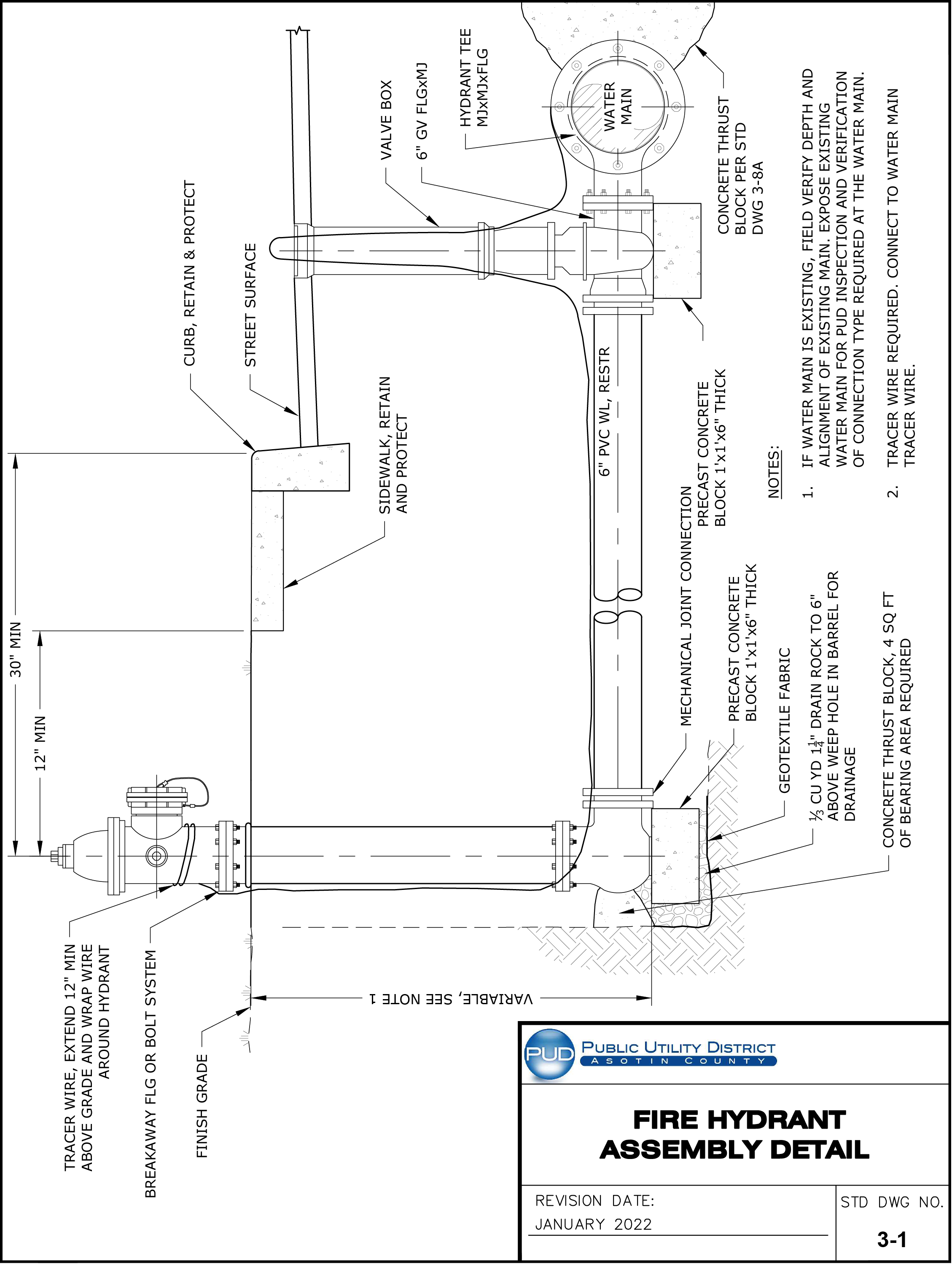
For the original technical drawing, see Construction Standards & Specifications PDF, PDF page 245 of 270.
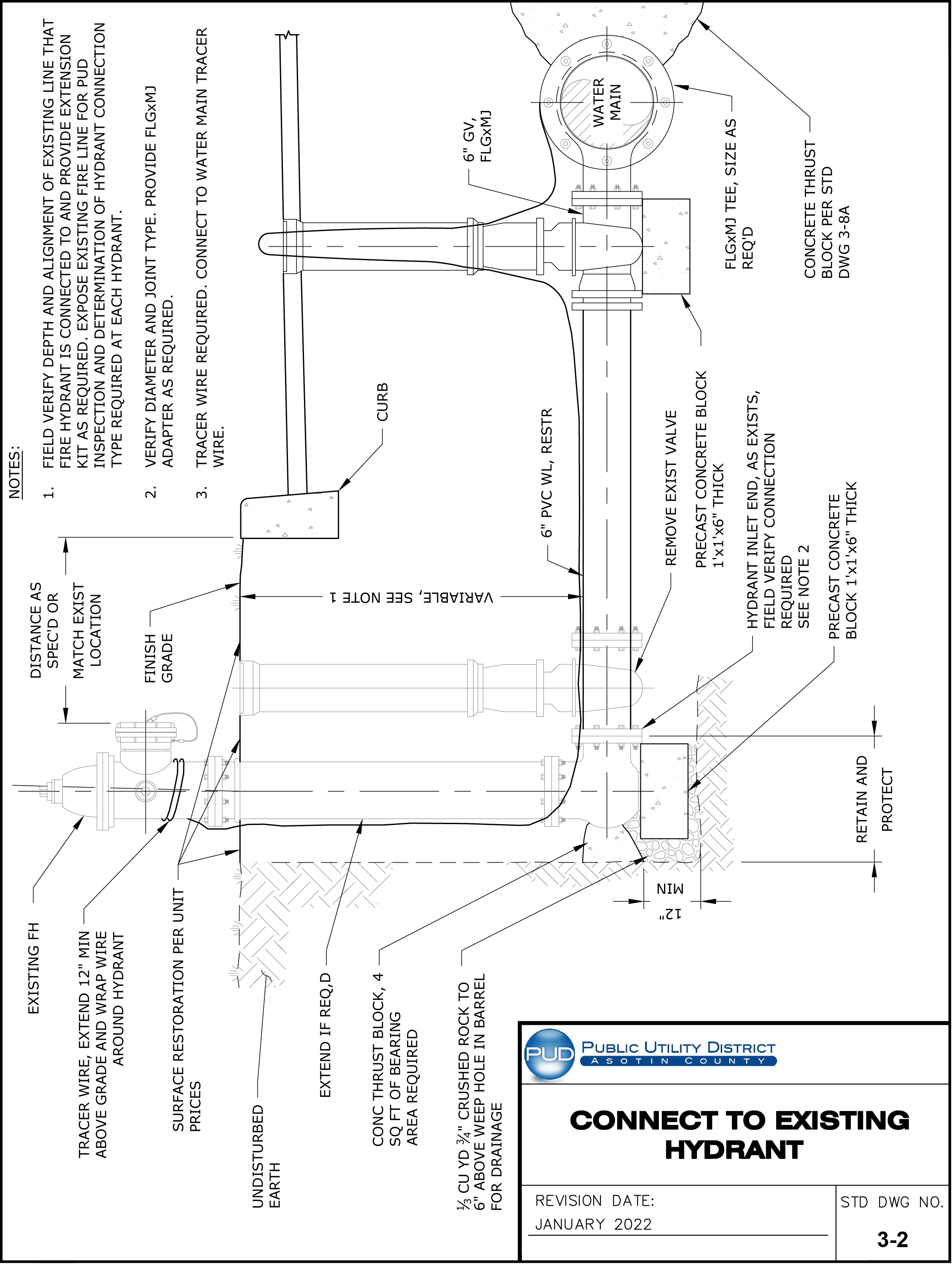
For the original technical drawing, see Construction Standards & Specifications PDF, PDF page 246 of 270.
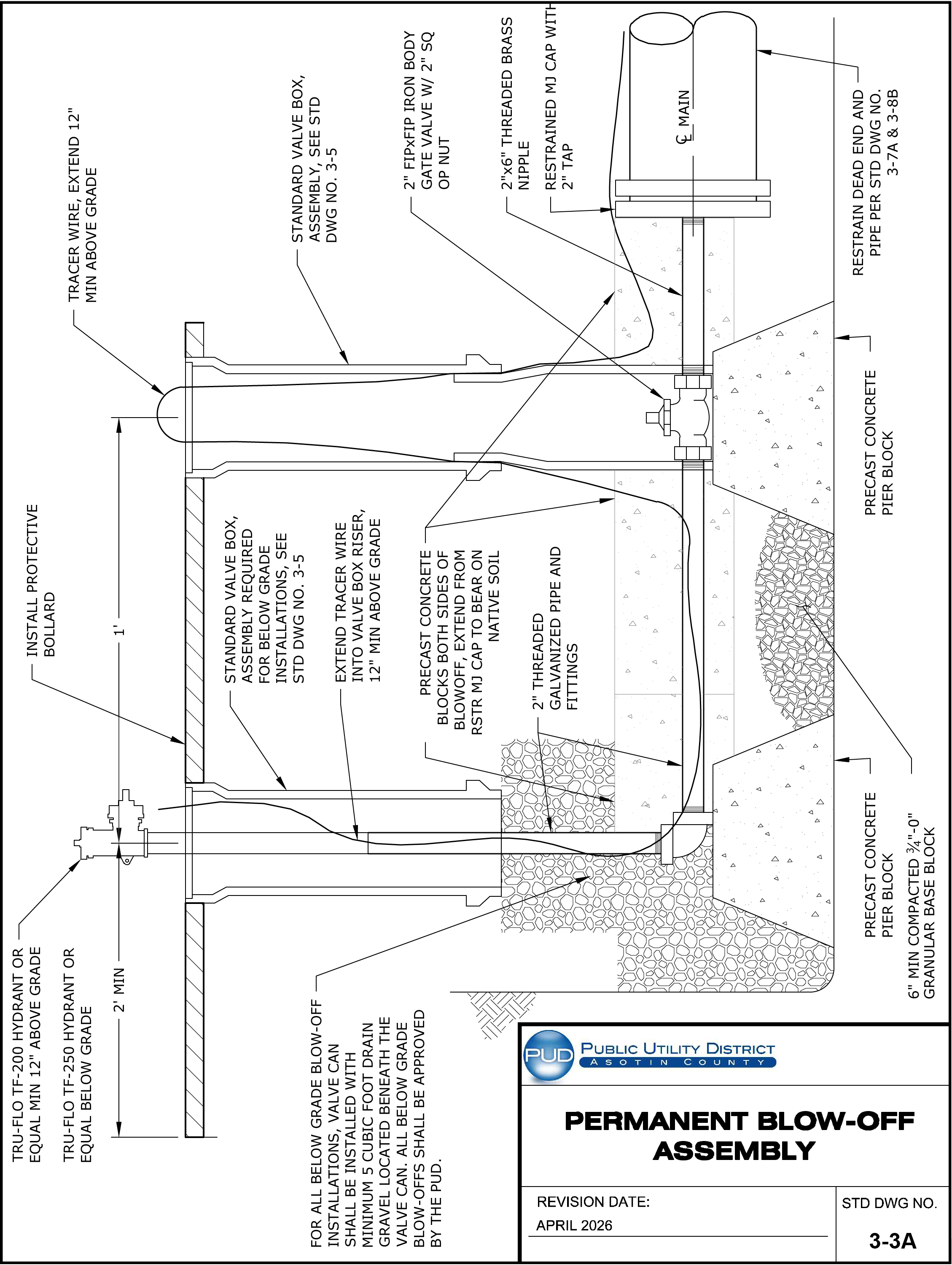
For the original technical drawing, see Construction Standards & Specifications PDF, PDF page 247 of 270.
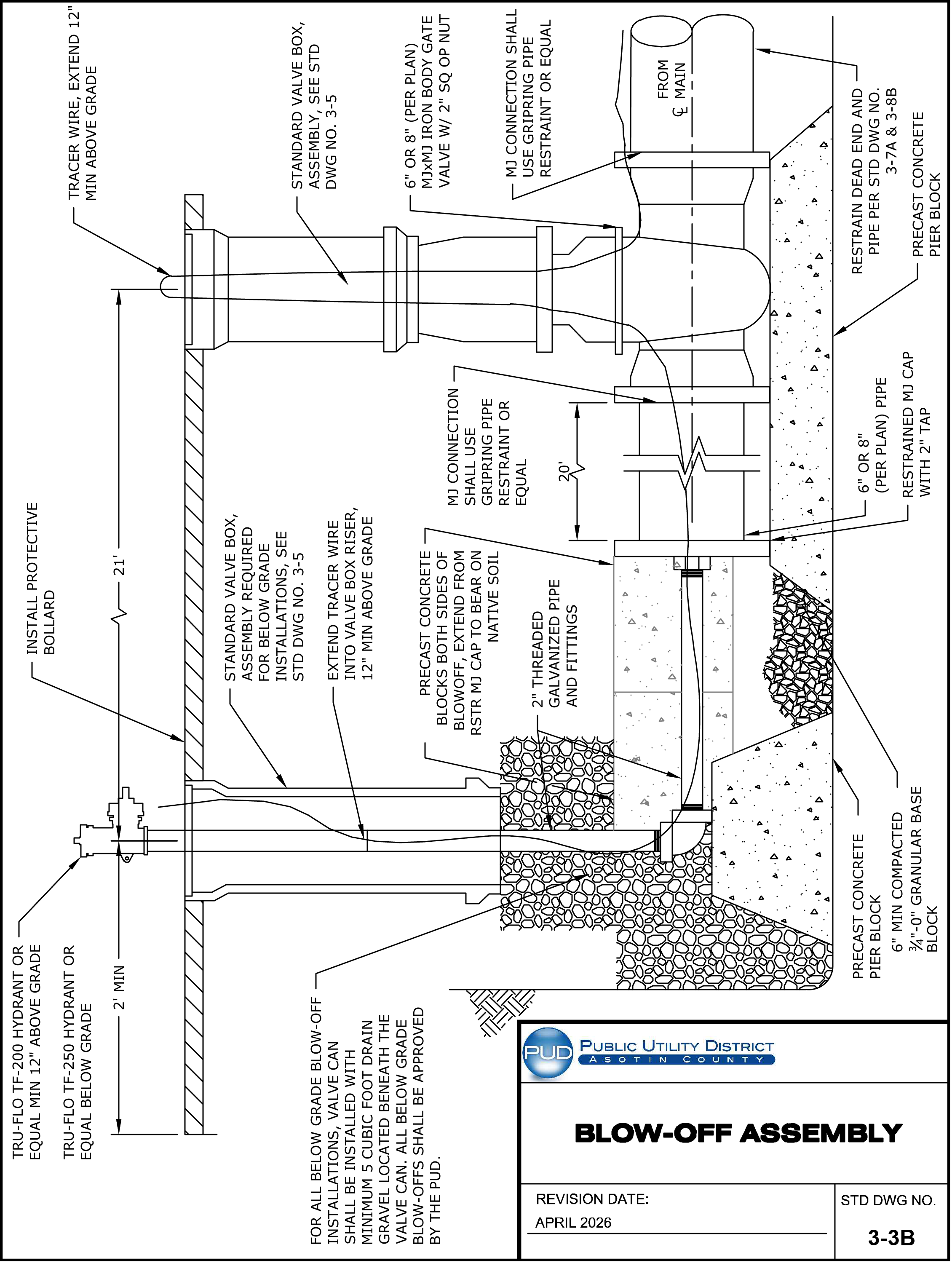
For the original technical drawing, see Construction Standards & Specifications PDF, PDF page 248 of 270.
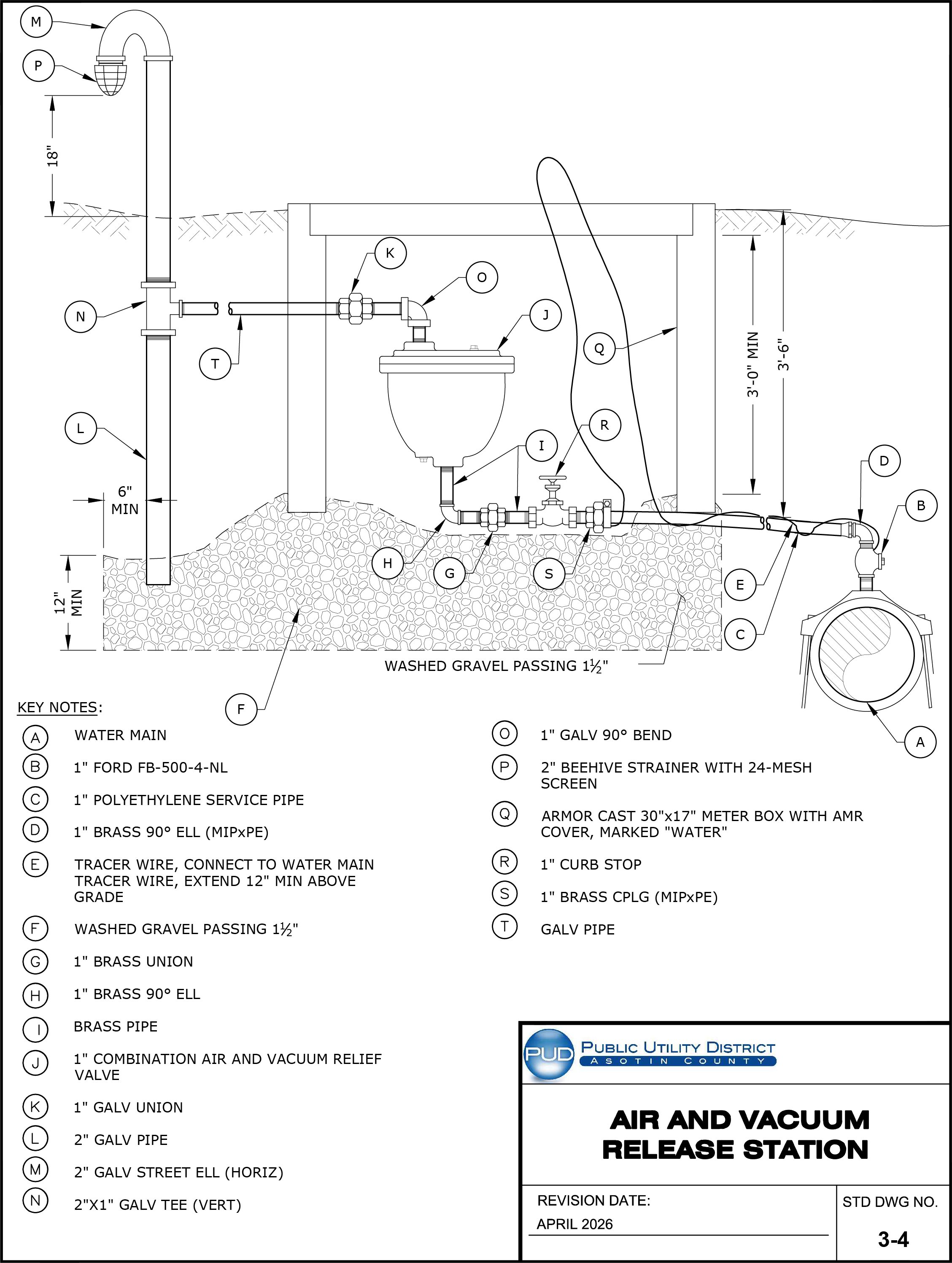
For the original technical drawing, see Construction Standards & Specifications PDF, PDF page 249 of 270.
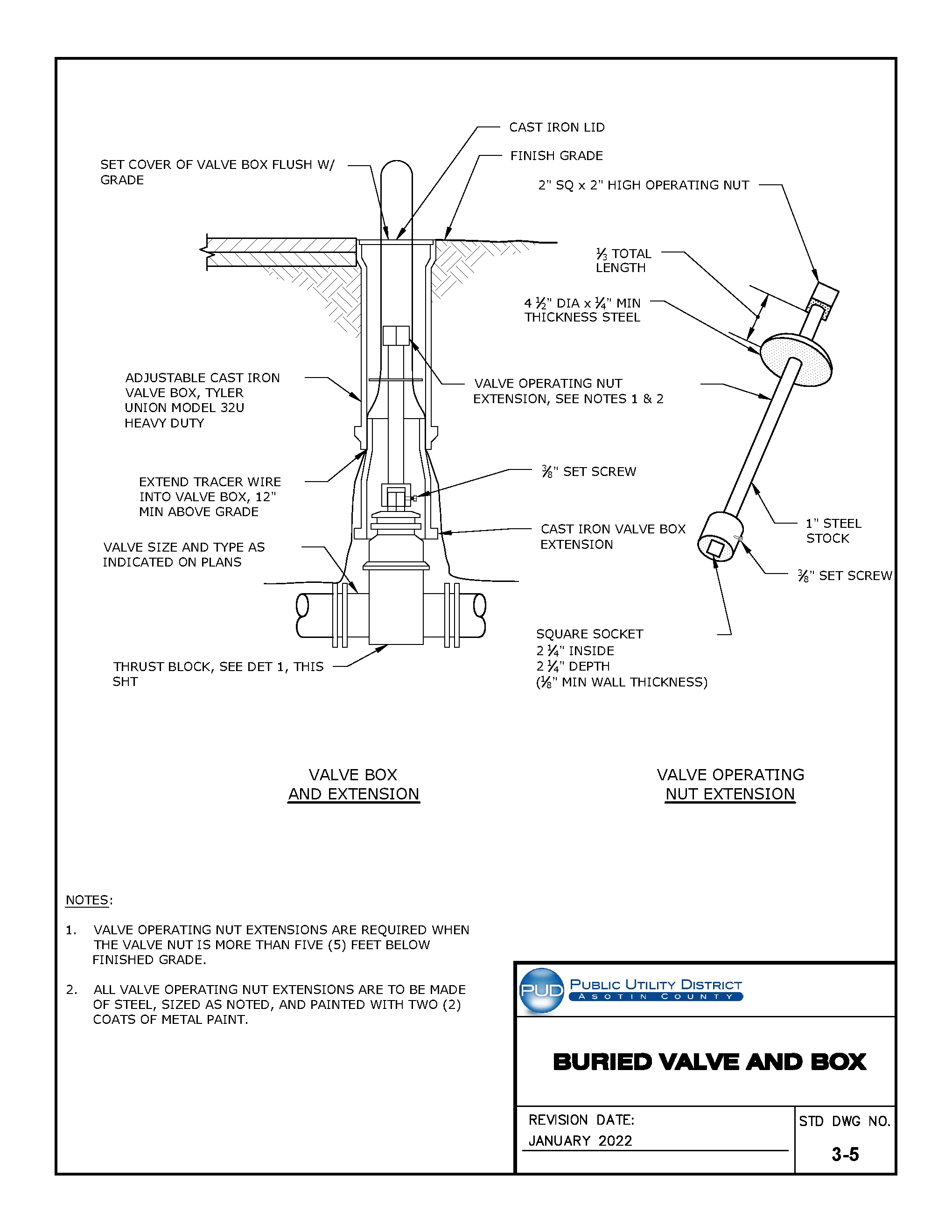
For the original technical drawing, see Construction Standards & Specifications PDF, PDF page 250 of 270.
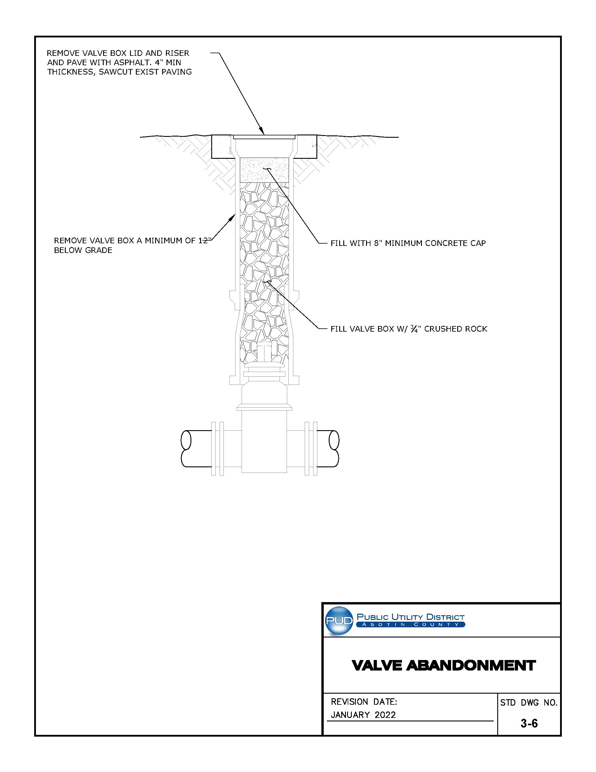
For the original technical drawing, see Construction Standards & Specifications PDF, PDF page 251 of 270.
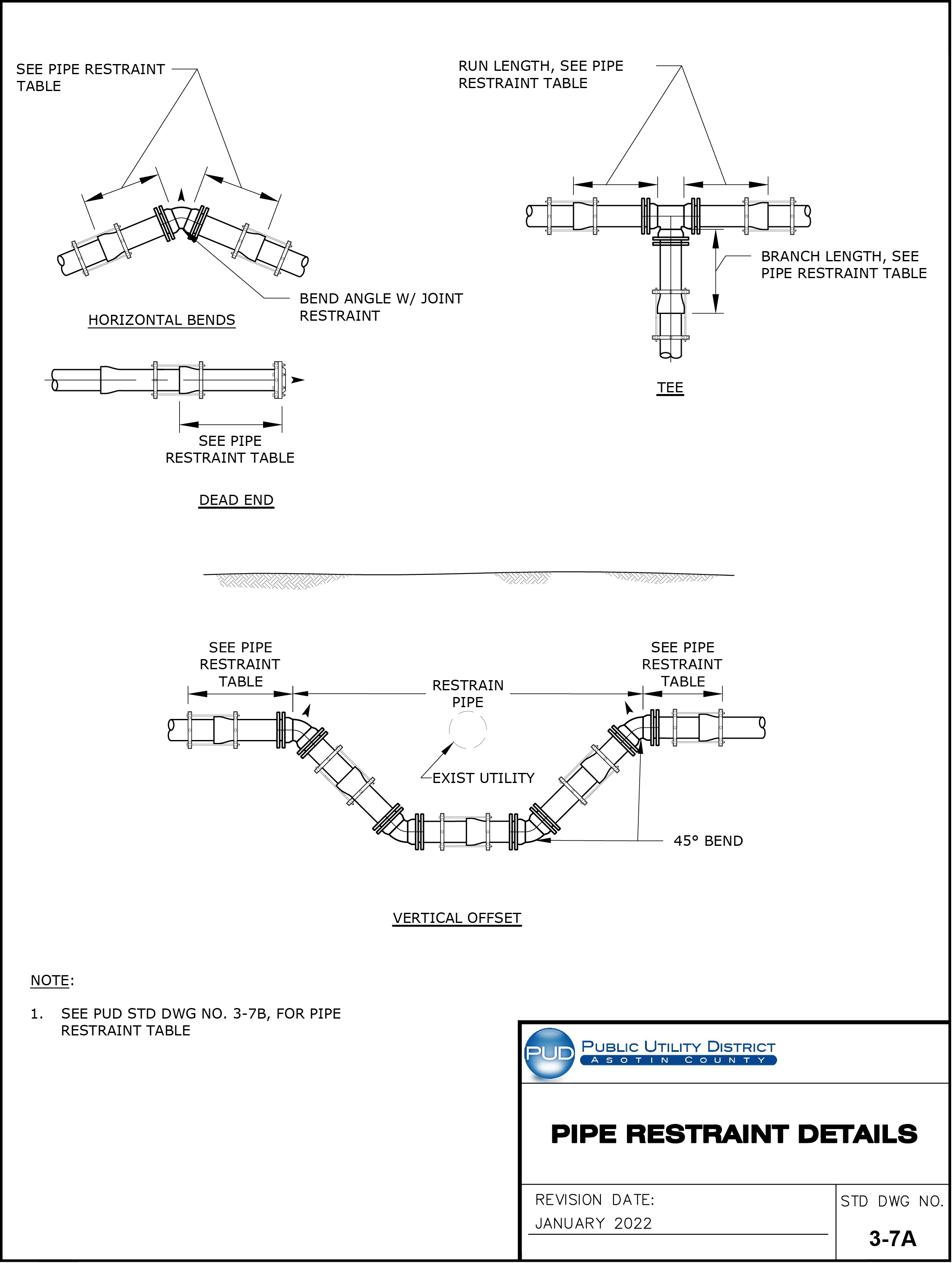
For the original technical drawing, see Construction Standards & Specifications PDF, PDF page 252 of 270.
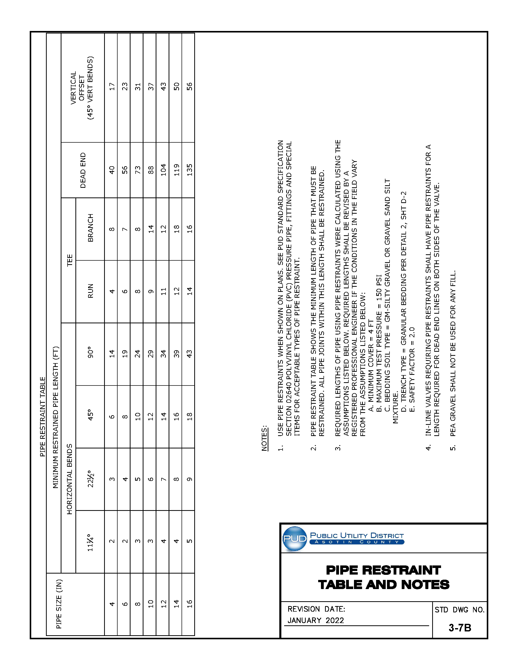
For the original technical drawing, see Construction Standards & Specifications PDF, PDF page 253 of 270.
Accessible drawing description
Pipe restraint table
| VERTICALOFFSET(45° VERT BENDS) | 17 | 23 | 31 | 37 | 43 | 50 | 56 | |||||||||
|---|---|---|---|---|---|---|---|---|---|---|---|---|---|---|---|---|
| USE PIPE RESTRAINTS WHEN SHOWN ON PLANS. SEE PUD STANDARD SPECIFICATIONSECTION 02640 POLYVINYL CHLORIDE (PVC) PRESSURE PIPE, FITTINGS AND SPECIALITEMS FOR ACCEPTABLE TYPES OF PIPE RESTRAINT. | ||||||||||||||||
| 2. PIPE RESTRAINT TABLE SHOWS THE MINIMUM LENGTH OF PIPE THAT MUST BERESTRAINED. ALL PIPE JOINTS WITHIN THIS LENGTH SHALL BE RESTRAINED. | ||||||||||||||||
| REQUIRED LENGTHS OF PIPE USING PIPE RESTRAINTS WERE CALCULATED USING THEASSUMPTIONS LISTED BELOW. REQUIRED LENGTHS SHALL BE REVISED BY AREGISTERED PROFESSIONAL ENGINEER IF THE CONDITIONS IN THE FIELD VARYFROM THE ASSUMPTIONS LISTED BELOW: | ||||||||||||||||
| MINIMUM COVER = 4 FTA. MAXIMUM TEST PRESSURE = 150 PSIB. BEDDING SOIL TYPE = GM-SILTY GRAVEL OR GRAVEL SAND SILT C. | ||||||||||||||||
| DEAD END | 40 | 56 | 73 | 88 | 104 | 119 | 135 | MIXTURE. TRENCH TYPE = GRANULAR BEDDING PER DETAIL 2, SHT D-2D. SAFETY FACTOR = 2.0E. | IN-LINE VALVES REQUIRING PIPE RESTRAINTS SHALL HAVE PIPE RESTRAINTS FOR ALENGTH REQUIRED FOR DEAD END LINES ON BOTH SIDES OF THE VALVE. | PEA GRAVEL SHALL NOT BE USED FOR ANY FILL. | ||||||
| TEE | BRANCH | 8 | 7 | 8 | 14 | 12 | 18 | 16 | ||||||||
| NOTES: | ||||||||||||||||
| RUN | 4 | 6 | 8 | 9 | 11 | 12 | 14 | |||||||||
| 90° | 14 | 19 | 24 | 29 | 34 | 39 | 43 | |||||||||
| 45° | 6 | 8 | 10 | 12 | 14 | 16 | 18 | |||||||||
| HORIZONTAL BENDS | 1. | 3. | 4. | 5. | ||||||||||||
Drawing notes
- USE PIPE RESTRAINTS WHEN SHOWN ON PLANS. SEE PUD STANDARD SPECIFICATION SECTION 02640 POLYVINYL CHLORIDE (PVC) PRESSURE PIPE, FITTINGS AND SPECIAL ITEMS FOR ACCEPTABLE TYPES OF PIPE RESTRAINT.
- PIPE RESTRAINT TABLE SHOWS THE MINIMUM LENGTH OF PIPE THAT MUST BE TABLE AND NOTES RESTRAINED. ALL PIPE JOINTS WITHIN THIS LENGTH SHALL BE RESTRAINED. PIPE RESTRAINT
- REQUIRED LENGTHS OF PIPE USING PIPE RESTRAINTS WERE CALCULATED USING THE ASSUMPTIONS LISTED BELOW. REQUIRED LENGTHS SHALL BE REVISED BY A REGISTERED PROFESSIONAL ENGINEER IF THE CONDITIONS IN THE FIELD VARY FROM THE ASSUMPTIONS LISTED BELOW: A. MINIMUM COVER = 4 FT B. MAXIMUM TEST PRESSURE = 150 PSI C. BEDDING SOIL TYPE = GM-SILTY GRAVEL OR GRAVEL SAND SILT MIXTURE. D. TRENCH TYPE = GRANULAR BEDDING PER DETAIL 2, SHT D-2 E. SAFETY FACTOR = 2.0
- IN-LINE VALVES REQUIRING PIPE RESTRAINTS SHALL HAVE PIPE RESTRAINTS FOR A LENGTH REQUIRED FOR DEAD END LINES ON BOTH SIDES OF THE VALVE. 3-7B 3-7B
- PEA GRAVEL SHALL NOT BE USED FOR ANY FILL.
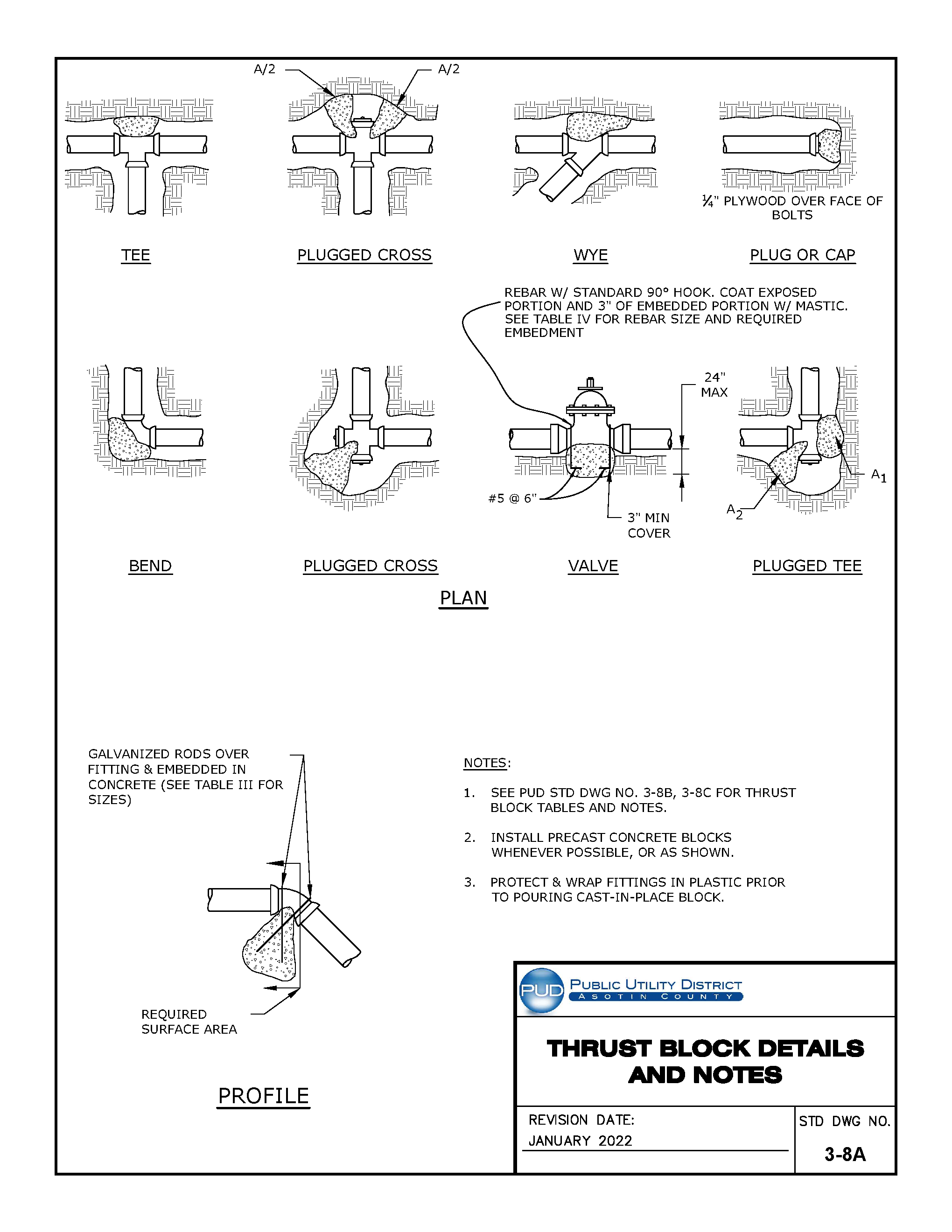
For the original technical drawing, see Construction Standards & Specifications PDF, PDF page 254 of 270.
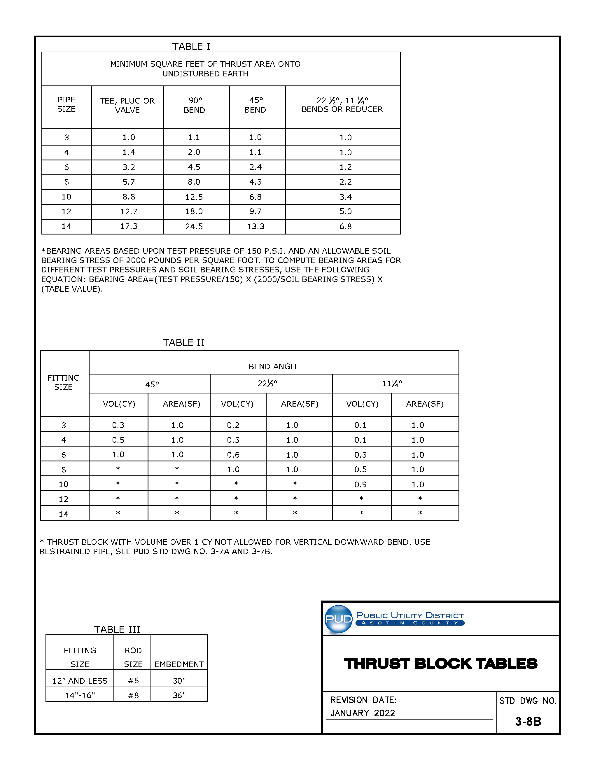
For the original technical drawing, see Construction Standards & Specifications PDF, PDF page 255 of 270.
Accessible drawing description
Table I
| TABLE I | ||||
|---|---|---|---|---|
| MINIMUM SQUARE FEET OF THRUST AREA ONTO UNDISTURBED EARTH | ||||
| PIPE SIZE | TEE, PLUG OR VALVE | 90° BEND | 45° BEND | 22 12°, 11 14 ° BENDS OR REDUCER |
| 3 | 1.0 | 1.1 | 1.0 | 1.0 |
| 4 | 1.4 | 2.0 | 1.1 | 1.0 |
| 6 | 3.2 | 4.5 | 2.4 | 1.2 |
| 8 | 5.7 | 8.0 | 4.3 | 2.2 |
| 10 | 8.8 | 12.5 | 6.8 | 3.4 |
| 12 | 12.7 | 18.0 | 9.7 | 5.0 |
| 14 | 17.3 | 24.5 | 13.3 | 6.8 |
BEARING AREAS BASED UPON TEST PRESSURE OF 150 P.S.I. AND AN ALLOWABLE SOIL BEARING STRESS OF 2000 POUNDS PER SQUARE FOOT. TO COMPUTE BEARING AREAS FOR DIFFERENT TEST PRESSURES AND SOIL BEARING STRESSES, USE THE FOLLOWING EQUATION: BEARING AREA=(TEST PRESSURE/150) X (2000/SOIL BEARING STRESS) X (TABLE VALUE).
Table II
| FITTING SIZE | BEND ANGLE | |||||
|---|---|---|---|---|---|---|
| 45° | 2212 ° | 1114° | ||||
| VOL(CY) | AREA(SF) | VOL(CY) | AREA(SF) | VOL(CY) | AREA(SF) | |
| 3 | 0.3 | 1.0 | 0.2 | 1.0 | 0.1 | 1.0 |
| 4 | 0.5 | 1.0 | 0.3 | 1.0 | 0.1 | 1.0 |
| 6 | 1.0 | 1.0 | 0.6 | 1.0 | 0.3 | 1.0 |
| 8 | * | * | 1.0 | 1.0 | 0.5 | 1.0 |
| 10 | * | * | * | * | 0.9 | 1.0 |
| 12 | * | * | * | * | * | * |
| 14 | * | * | * | * | * | * |
* 1.0 1.0 0.5 1.0 8 * * * * 10 0.9 1.0 * * * * * * 12 * * * * * * 14 * THRUST BLOCK WITH VOLUME OVER 1 CY NOT ALLOWED FOR VERTICAL DOWNWARD BEND. USE RESTRAINED PIPE, SEE PUD STD DWG NO.
Table III
| TABLE III | ||
|---|---|---|
| FITTING SIZE | ROD SIZE | EMBEDMENT |
| 12" AND LESS | #6 | 30" |
| 14"-16" | #8 | 36" |
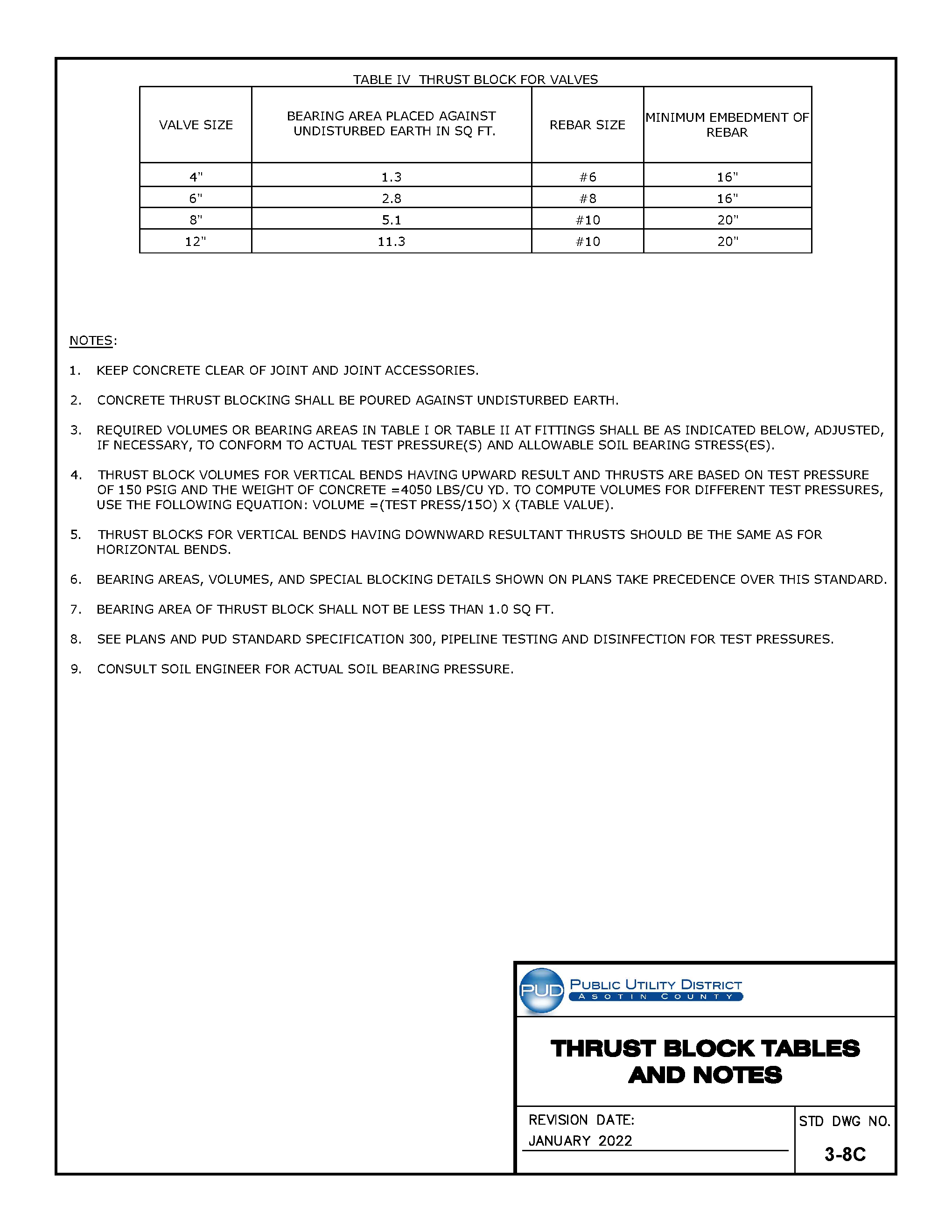
For the original technical drawing, see Construction Standards & Specifications PDF, PDF page 256 of 270.
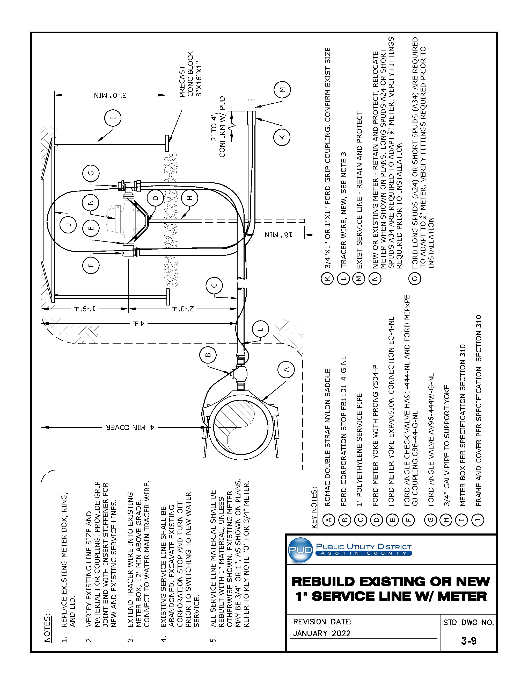
For the original technical drawing, see Construction Standards & Specifications PDF, PDF page 257 of 270.
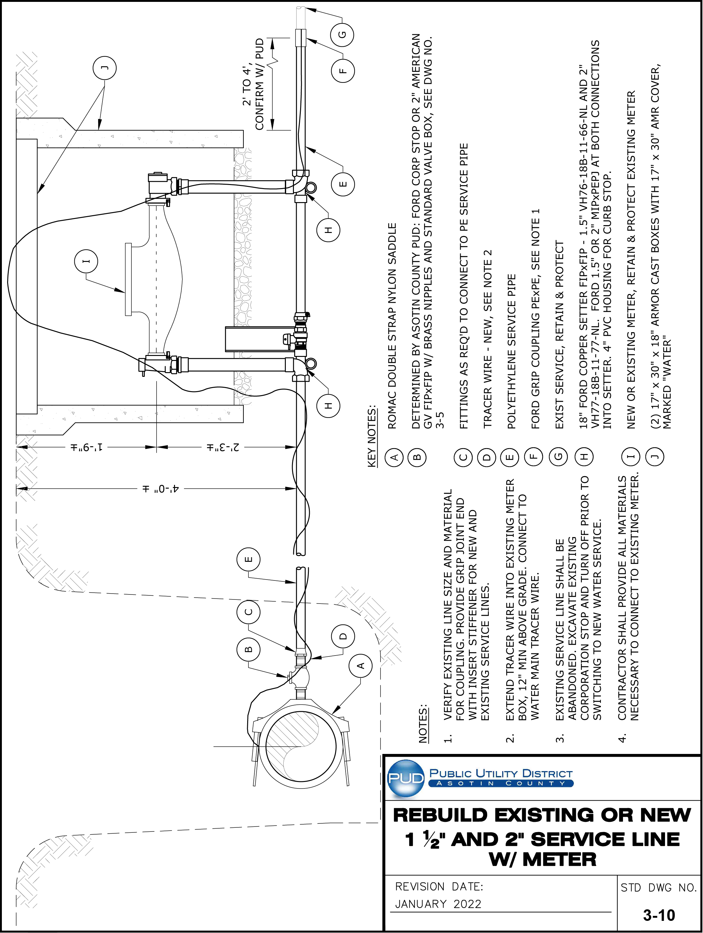
For the original technical drawing, see Construction Standards & Specifications PDF, PDF page 258 of 270.
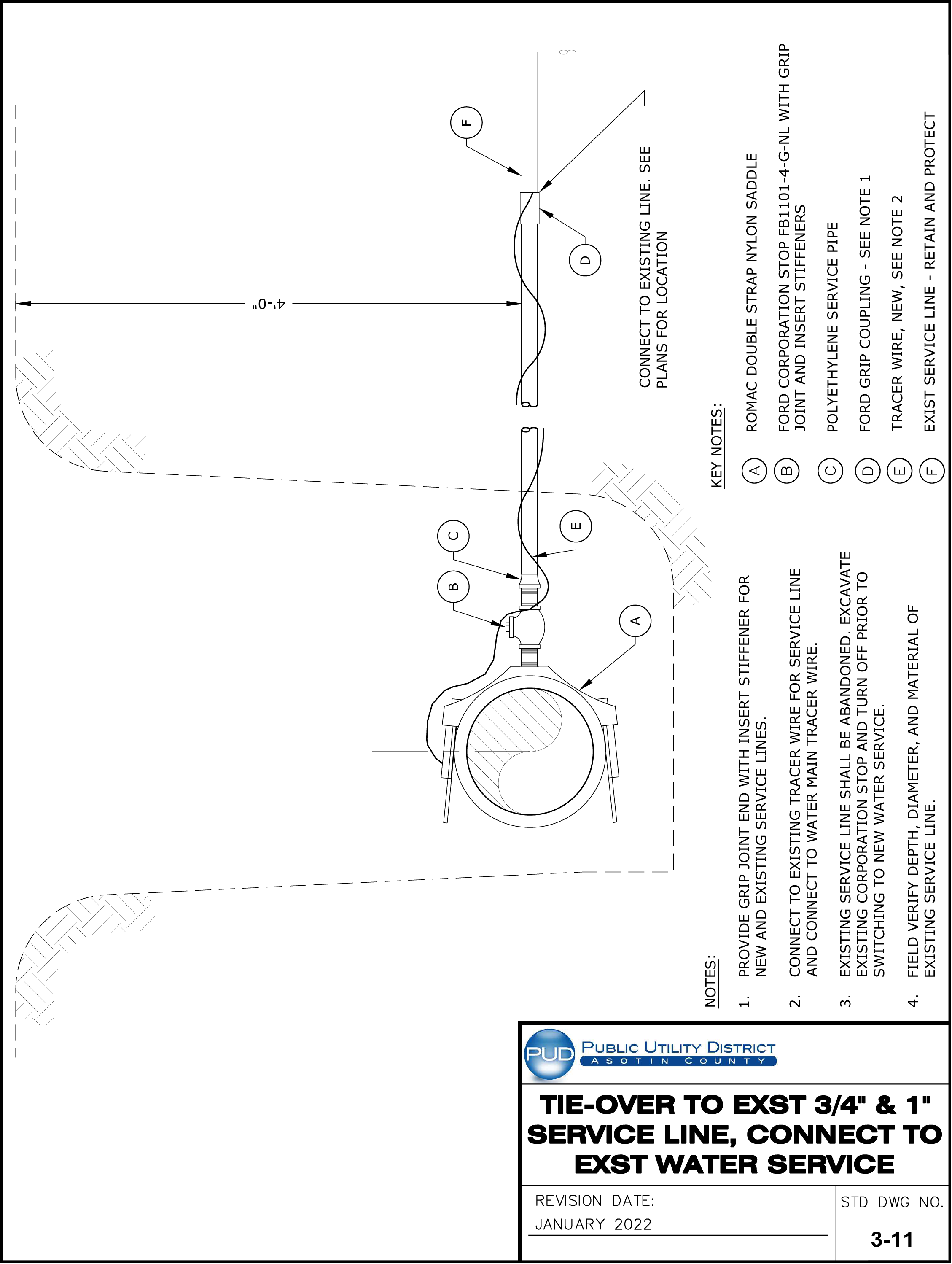
For the original technical drawing, see Construction Standards & Specifications PDF, PDF page 259 of 270.
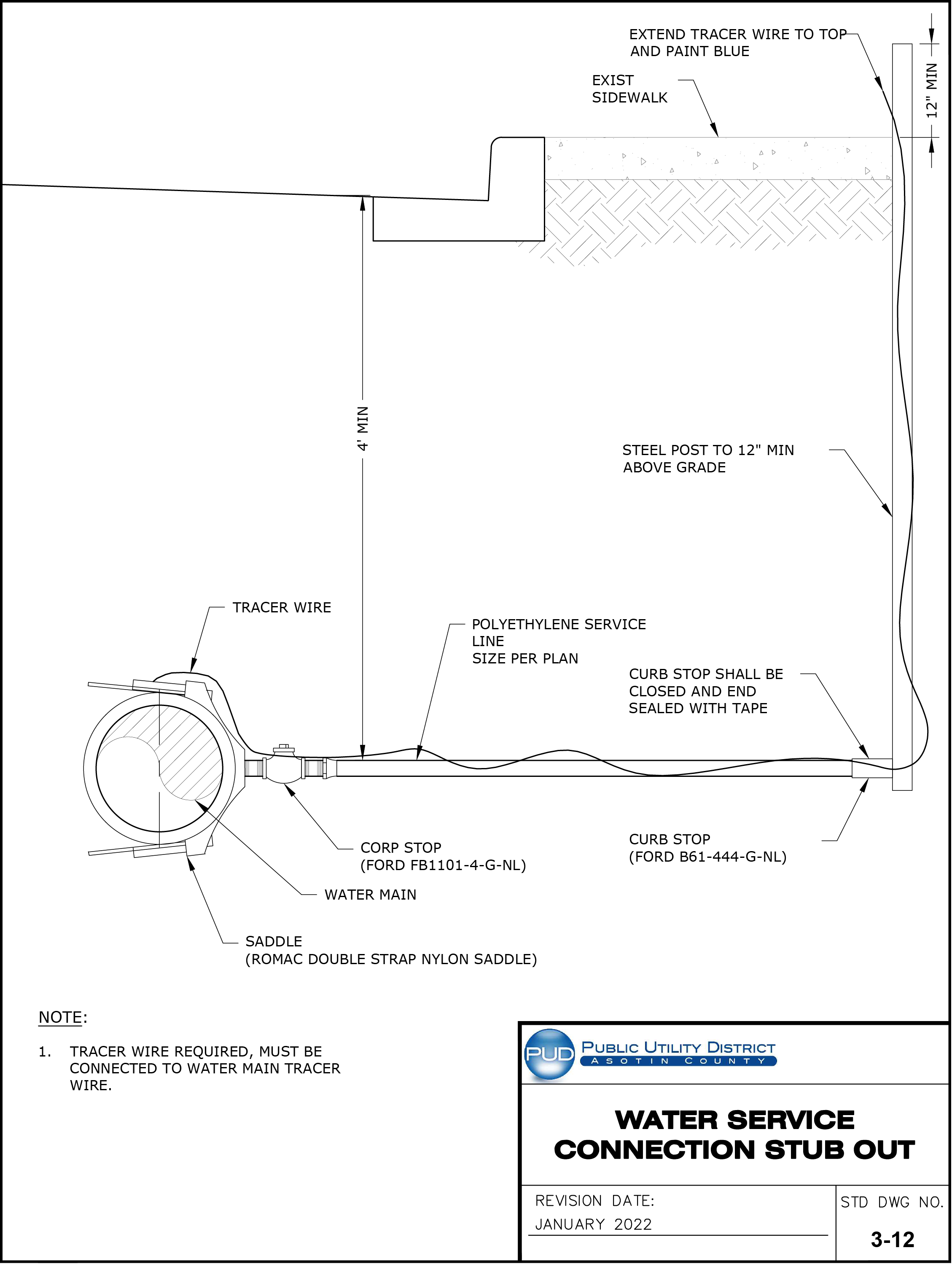
For the original technical drawing, see Construction Standards & Specifications PDF, PDF page 260 of 270.
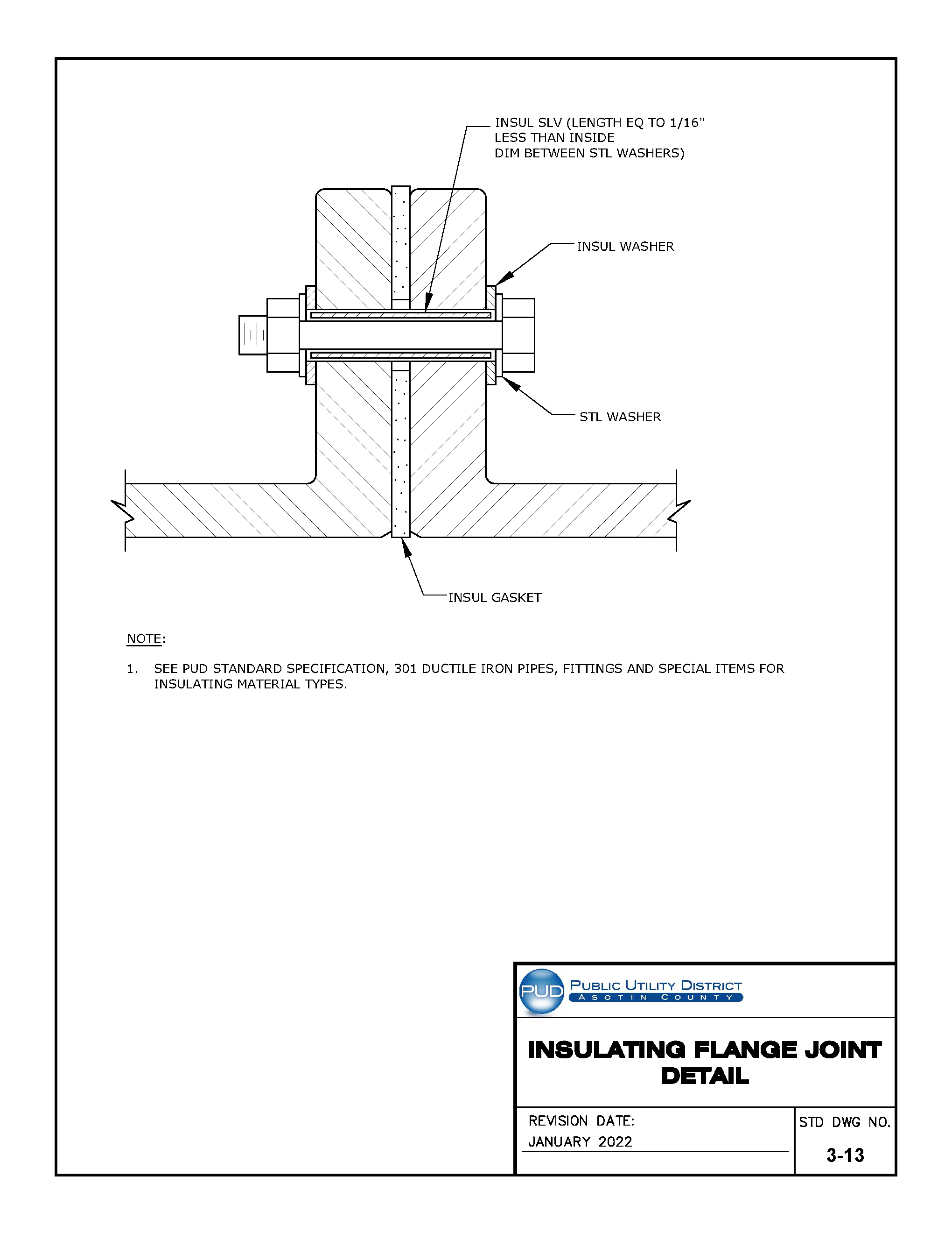
For the original technical drawing, see Construction Standards & Specifications PDF, PDF page 261 of 270.
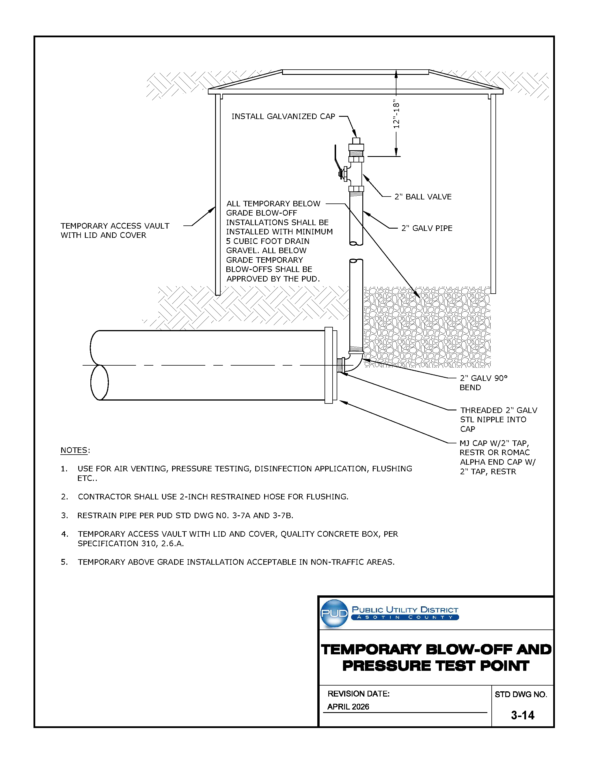
For the original technical drawing, see Construction Standards & Specifications PDF, PDF page 262 of 270.
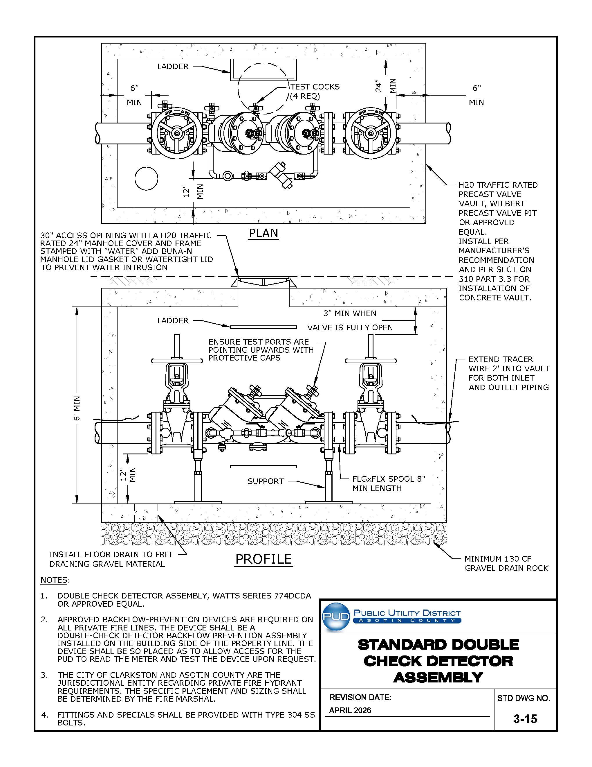
For the original technical drawing, see Construction Standards & Specifications PDF, PDF page 263 of 270.
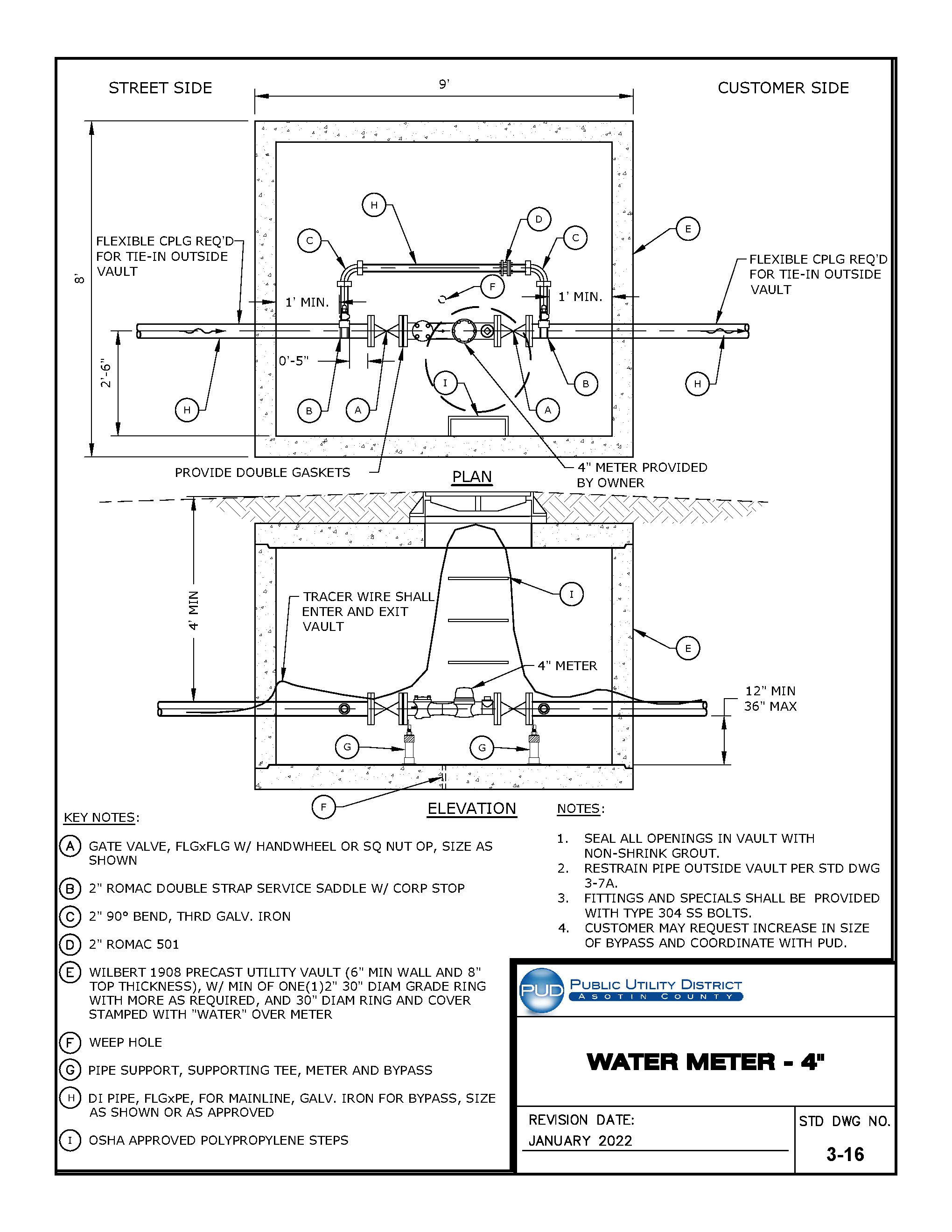
For the original technical drawing, see Construction Standards & Specifications PDF, PDF page 264 of 270.
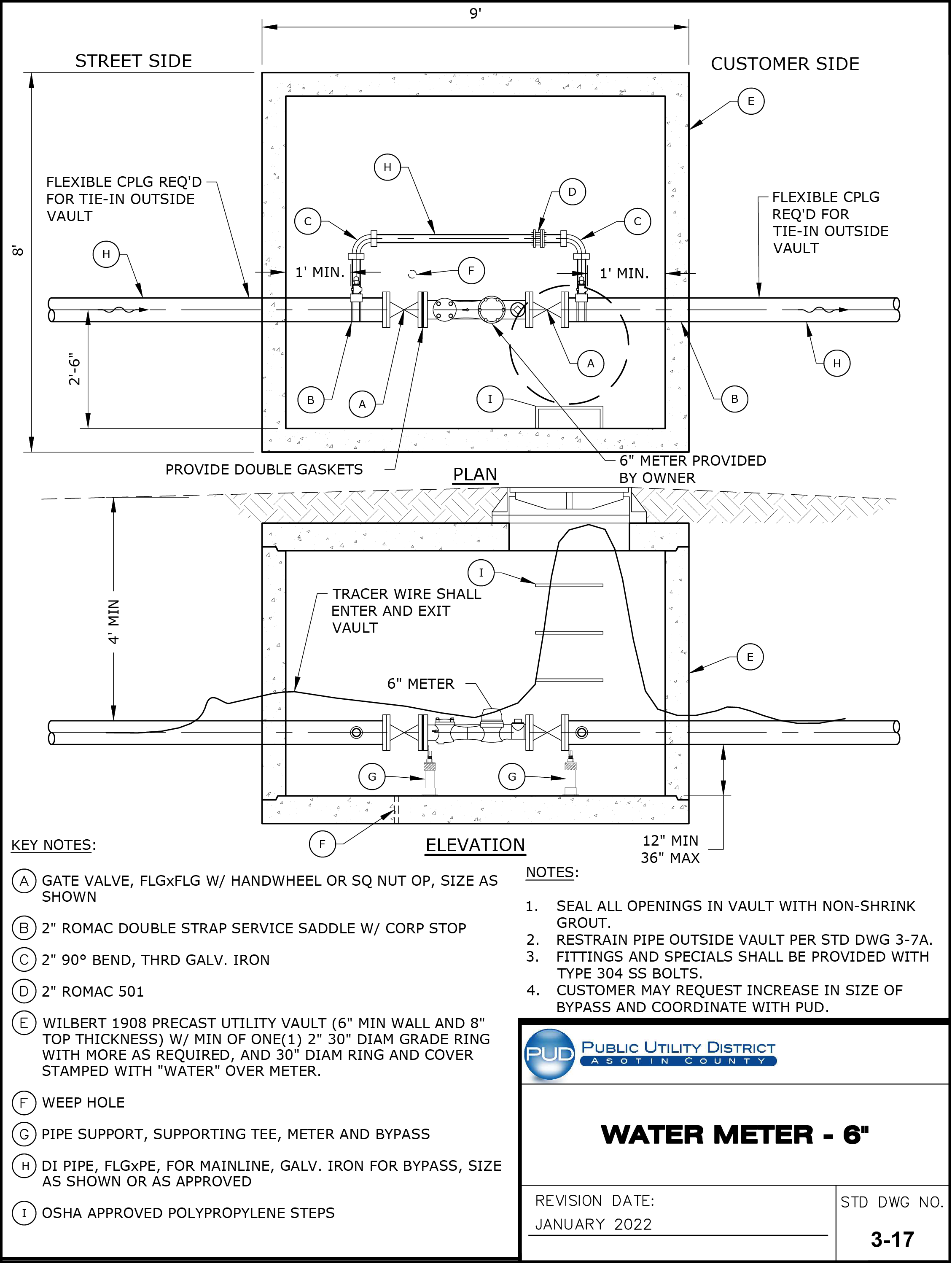
For the original technical drawing, see Construction Standards & Specifications PDF, PDF page 265 of 270.
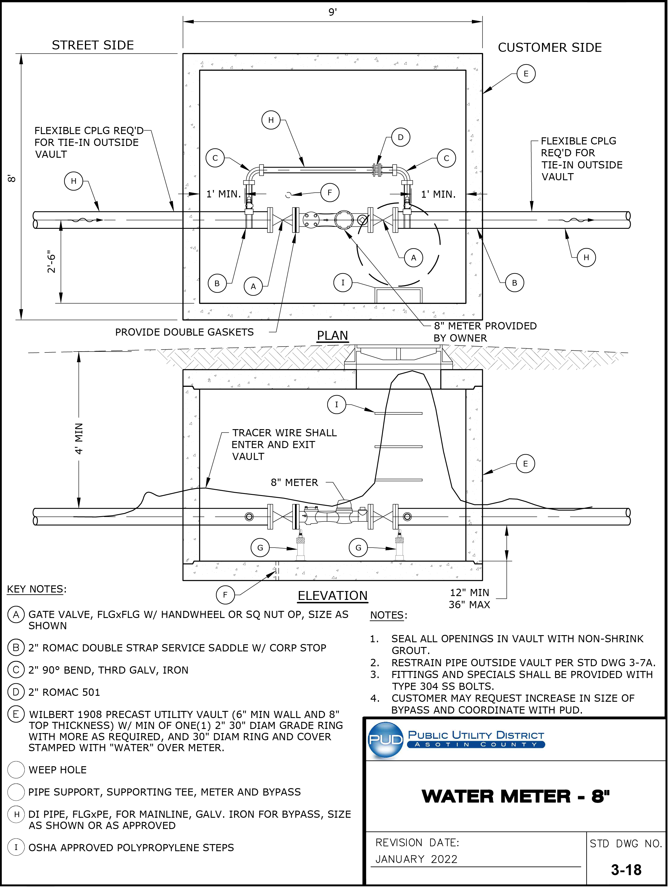
For the original technical drawing, see Construction Standards & Specifications PDF, PDF page 266 of 270.
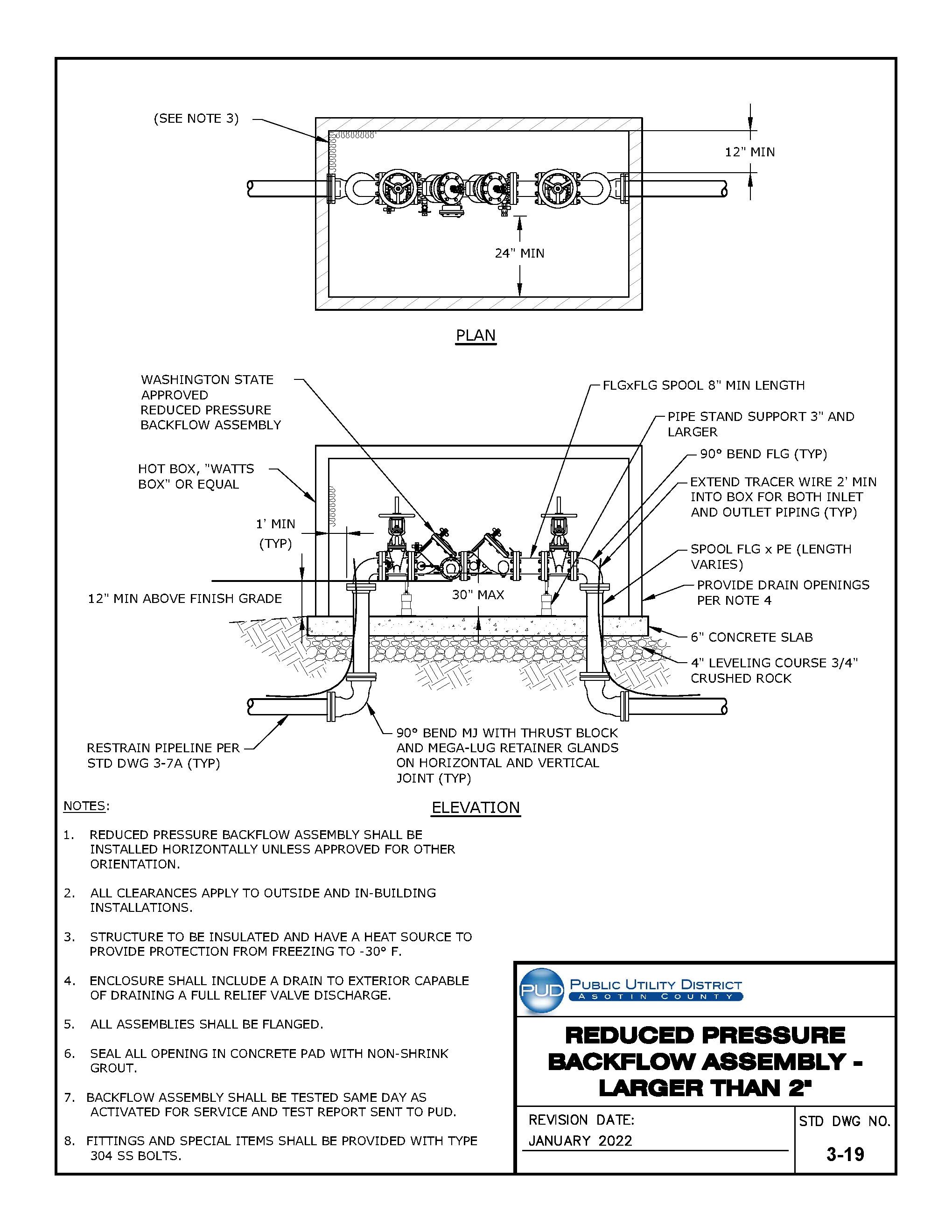
For the original technical drawing, see Construction Standards & Specifications PDF, PDF page 267 of 270.
Accessible drawing description
Drawing notes
- REDUCED PRESSURE BACKFLOW ASSEMBLY SHALL BE INSTALLED HORIZONTALLY UNLESS APPROVED FOR OTHER ORIENTATION.
- ALL CLEARANCES APPLY TO OUTSIDE AND IN-BUILDING INSTALLATIONS.
- STRUCTURE TO BE INSULATED AND HAVE A HEAT SOURCE TO PROVIDE PROTECTION FROM FREEZING TO -30° F.
- ENCLOSURE SHALL INCLUDE A DRAIN TO EXTERIOR CAPABLE OF DRAINING A FULL RELIEF VALVE DISCHARGE.
- ALL ASSEMBLIES SHALL BE FLANGED.
- SEAL ALL OPENING IN CONCRETE PAD WITH NON-SHRINK GROUT.
- BACKFLOW ASSEMBLY SHALL BE TESTED SAME DAY AS ACTIVATED FOR SERVICE AND TEST REPORT SENT TO PUD.
- FITTINGS AND SPECIAL ITEMS SHALL BE PROVIDED WITH TYPE 304 SS BOLTS. 3-19
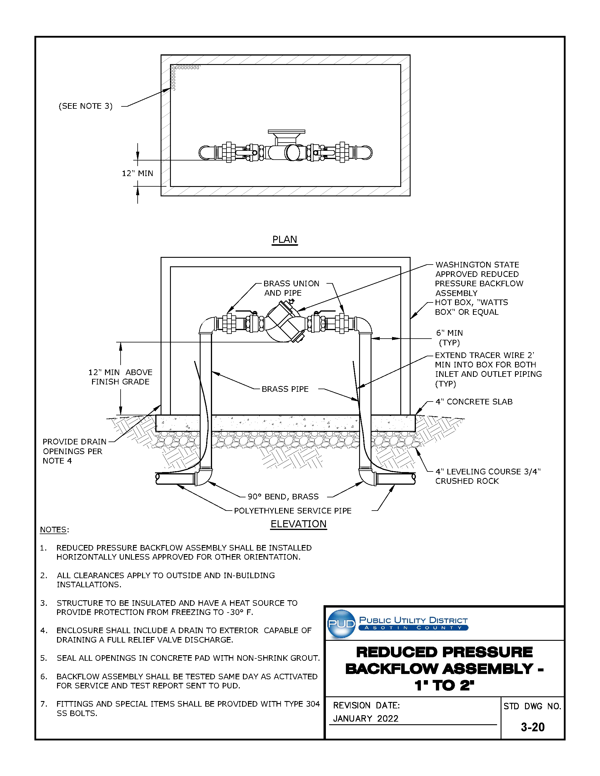
For the original technical drawing, see Construction Standards & Specifications PDF, PDF page 268 of 270.
What is Backflow?
Water systems depend on water pressure to keep flow in the proper direction through pipes and hoses. However, anything that causes a drop in water pressure can create a reverse flow, such as from a home’s plumbing system back into the public water system. This is called backflow.
Why is Backflow Important?
Our community’s water supply can become unsafe and unhealthy when backflow occurs and the plumbing system comes in contact with contaminants through backflow.
Preventing Backflow
To protect our community’s water system, backflow prevention assemblies are required if you have underground sprinkler systems.
Backflow Prevention For Landscape Irrigation Systems
The three types of acceptable backflow assemblies are shown to the right:
Pressure Vacuum Breaker Assembly
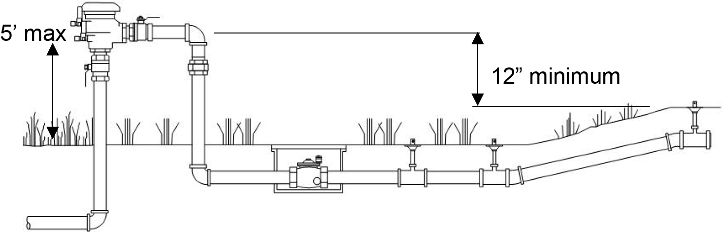
For the original technical diagram, see Construction Standards & Specifications PDF, PDF page 269 of 270.
Accessible drawing description
Diagram labels: 5 feet maximum and 12 inches minimum.
Installation requirements are provided in the adjacent document content.
• The Pressure Vacuum Break Assembly (PVBA) may be installed to isolate all irrigation systems that do not use injectors or pumps to apply fertilizer and other agricultural chemicals.5’ max 12” minimum• The PVBA shall be installed at least 12 inches above the highest point in the irrigation piping and no more than 5 feet above ground level.
Reduced Pressure Backflow Assembly
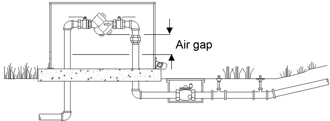
For the original technical diagram, see Construction Standards & Specifications PDF, PDF page 269 of 270.
Accessible drawing description
Installation requirements are provided in the adjacent document content.
• The Reduced Pressure Backflow Assembly (RPBA) should be installed to isolate irrigation systems using injectors or pumps to apply fertilizer and other agricultural chemicals.Air gap• Reduced pressure backflow assemblies must be installed above ground level.• An approved air gap is required under the relief valve port.
Double Check Valve Assembly
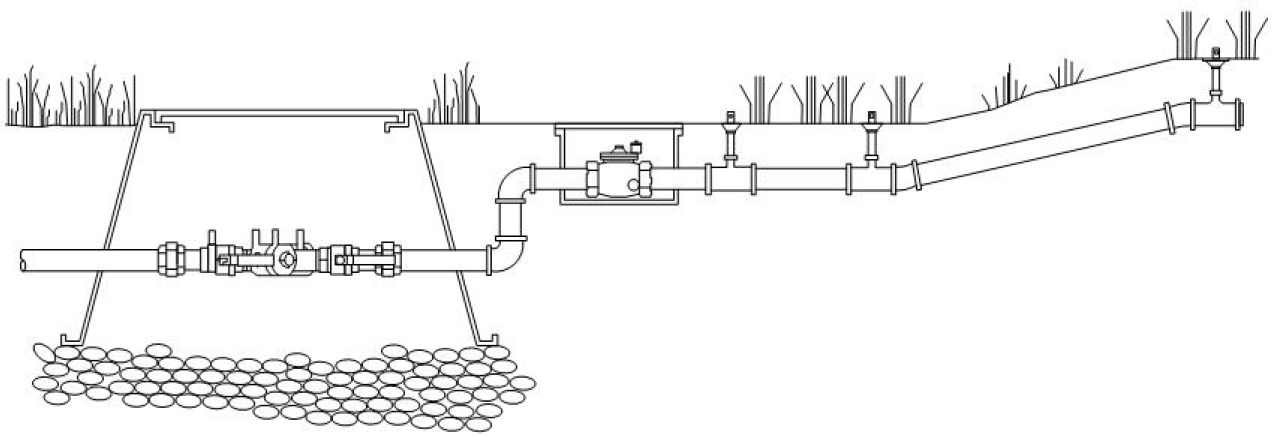
For the original technical diagram, see Construction Standards & Specifications PDF, PDF page 269 of 270.
Accessible drawing description
Installation requirements are provided in the adjacent document content.
• The Double Check Valve Assembly (DCVA) may be installed to isolate all irrigation systems that do not use injector or pumps to apply fertilizer and other agricultural chemicals.• The DCVA may be installed in above ground or in a below-ground enclosure.
Asotin County PUD water customers are responsible for compliance with the following general installation guidelines:
• Assemblies may not be installed in ceilings, walls or crawl spaces.• Assemblies must be installed with adequate clearance for testing and maintenance.• You must obtain a plumbing permit before you install a backflow preventer.• Assemblies must be installed according to the requirements of Asotin County PUD and must be installed by a certified Backflow Assembly Tester.• All assemblies must be on the Washington State Approved Backflow Assembly List available through the Department of Health, (360) 236-3100/1-800-521-0323.• Assemblies must be tested when they are first installed, after repair or relocation, and annually after installation by a State of Washington-certified Backflow Assembly Tester.• A list of state-certified testers in the Asotin County PUD water service area is available from the Washington Department of Health, (360) 236-3141 or (800) 525-2536.
Asotin County Public Utility District
1500 Scenic Way
P.O. Box 605
Clarkston, WA 99403
Phone: 509-758-1010
Fax: 509-758-1958
pudservice@asotinpud.org
Learn more at
www.asotinpud.org/
www.asotinpud.org/backflowprevention.html
Asotin County PUD Sprinkler Backflow Guidance Document
Important Information about the PUD’s Backflow Prevention Program and Your Responsibilities as a Property Owner